

More Guest Blogs


Editor’s note: This is one in a series of blogs detailing the construction of a net-zero energy house in Point Roberts, Washington, by an owner-builder with relatively little building experience. A list of Matt Bath’s GBA articles can be found at the bottom of this page. You’ll find Matt Bath’s full blog, Saving Sustainably, here. If you want to follow project costs, you can keep an eye on a budget worksheet here.
My net-zero home will be all-electric, in hopes that someday I can move from net-zero to completely self-sustaining and off-grid as technology improves. Battery prices are dropping rapidly and in my opinion it is only a matter of time before the electrical grid becomes a thing of the past. (If you aren’t a believer, check out this presentation by Tony Seba, a Stanford professor who has spent his life researching the advancement of technology.)
Fully electric houses require larger service entrance panels that contain space for more circuits than those of the average fossil-fuel house. This is absolutely not to be confused with a higher power rated service entrance panel. If you build your net-zero home properly and buy the right appliances, you won’t use any more power than the average home that uses electricity and fossil fuels.
I started with a list of all the circuits I would have, as well as the breaker and wire gauge sizes, all of which I will explain shortly. [Editor’s note: Wiring is potentially hazardous. Check with your local building office on whether a licensed electrician is required to do the work. Know your local codes, and never proceed when you are in doubt.]
The modern electrical service uses two nominal 120-volt “phases” of electricity that cancel each other out (nominal meaning they won’t actually be exactly 120 and will vary). This allows you to power circuits with either 120 or 240 nominal voltage.
Some circuits that use a lot of power take up two spaces in the main panel. These are 240-volt circuits. The first step in installing the electrical work is the same as with almost every step in the building process. You’ve got to have a detailed plan. That means deciding where all your receptacles, lighting fixtures, smoke alarms, and appliances will go, and what types of appliances you will have.
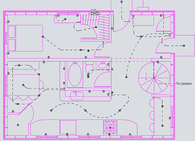
Locating receptacles and light fixtures
Receptacles must be located on every wall that is greater than 2 feet long and be placed no greater than 12 feet away from another receptacle along the same wall or an adjoining wall. On kitchen countertops, this distance is reduced to 4 feet. Additional outlets may be desired for areas with computer equipment or television screens. For example, I will be using Japanese-style toilets so I needed to install receptacles behind the toilet locations. The toilets will help me save sustainably by eliminating toilet paper waste, which in turn will help my septic system remain in good condition.
Receptacles can be placed at any height below 66 inches. I used an 18-inch mark on a piece of scrap wood to ensure that all of my receptacles were the same height. I used another scrap piece of wood to ensure that the boxes were spaced 1/2 inch out from the stud so that they will be flush with the drywall.
Every room must have an operable light fixture. Three-way light switches must be installed in stairways so the light fixture can be operated from either the top to the bottom of the staircase. More than one light fixture per room probably will be desired. Recessed lighting is attractive but not advisable when placed under an unconditioned space due to the difficulty in air sealing them. Surface-mounted LED lights are a newer technology that is hardly distinguishable from recessed lighting but much easier to air seal.
Every bedroom must have a smoke alarm, and an additional smoke alarm must be installed near the sleeping areas on each floor of the house. Smoke alarms must be wired in series together so that if one of them detects smoke they will all go off.
Be sure to check with your local electric utility to see if rebates are offered and save sustainably by balancing the cost of the appliance with the yearly operating cost. Check the specifications for each appliance and note the breaker size (also known as overcurrent protection) and voltage required. Appliances that say 120/240 need both 120 volts and 240 volts.
Additional wiring may be desired for doorbell, internet, speakers, and security. You may also want to provide additional circuits for the future. For example, I don’t currently own an electric car but I am fairly certain I will in the future so I included wiring for a charger.
Running cable for receptacles and appliances
With all of the gang boxes nailed into place, it was time to run the cables from the main panel to each outlet. Bear in mind that what we refer to in English as an electrical outlet is known as a “receptacle” in the electrical code.
When I refer to an outlet as an electrician, I am talking about the location where electricity will be utilized. This could be a receptacle, but it also could be a light or an appliance. The wires will carry the electrical current from the panel to the outlets. Most electricians use use NM-B type wire, commonly known by its trademark name, Romex. Standard Romex contains two (one white and one black) or three (white, red, and black) insulated conductors, and a paper-wrapped copper ground wire, all bundled together and wrapped in its own paper and insulation.
The paper might seem dangerous, but it is treated and it allows the wires inside to shift and slide without as much friction, making installation much easier. For any appliance you wish to power, you first need to decide whether to use Romex with two conductors or three. Appliances that require 120 or 240 volts only need two conductors. Appliances that say 120/240 require both voltages and you must run a three conductor cable to power them. You also use three-conductor wire for smoke alarms and for lights that are controlled by multiple switches.
The next thing you need to decide is what size conductors you need to use. The more current a given appliance needs, the bigger the wire should be to ensure the voltage doesn’t drop significantly by the time it reaches the appliance, and the wire doesn’t heat up so much to melt the insulation and cause a fire.
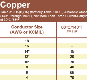
Properly sizing conductors can be quite involved, but doesn’t need to be when dealing with residential construction under normal circumstances. It can usually be simplified to just using the table above found in the NEC (National Electrical Code), unless the appliance is going to be running continuously.
As you can see, from the chart below, I listed all of the wire sizes for each circuit. In this way, I was able to plan which route each wire would take from the main panel to the outlet it is powering. When several wires take the same route, that is referred to as a raceway. It helps to plan out raceways in advance so you can drill one big hole that is just the right size for the wires instead of a bunch of smaller holes for each individual wire.
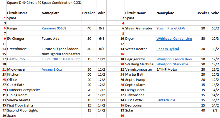
It is easier to start by running the larger wires first, and then run the smaller wires around them. For example, the first wire I ran was one of the bigger ones, for my induction range. The manufacturer states it requires a 40-amp circuit, with access to both 120 and 240 volts, so using the table above, the circuit requires 8-3 cable.
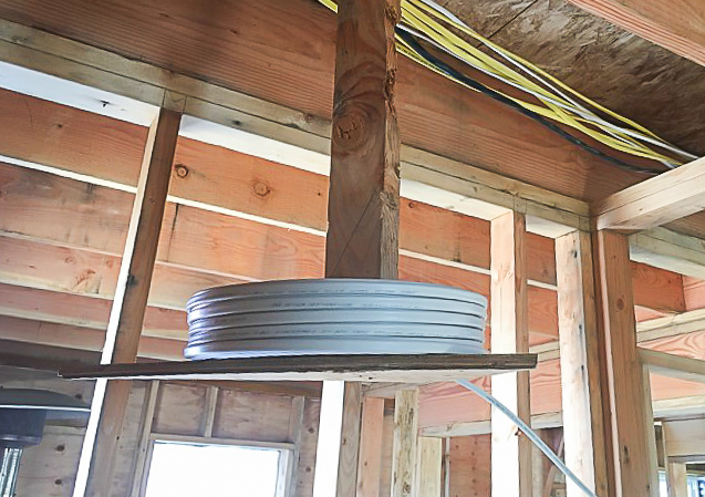
Circuits for appliances like the range are very simple, and usually consist of just a single cable. Once I had wired all of the appliances, I started on the circuits for the receptacles. Each of these circuits contains multiple receptacles, so you run a wire to the first gang box, and then another wire from the first box to the second box, and so on.
Building codes require some receptacle circuits to be on their own, such as those in bathrooms and the garages. Kitchens must have two separate receptacle circuits, although one can be combined with the dining room as I did. This is to ensure that several high powered items like blenders, hair dryers, power tools, etc. can be used at the same time without using up all the available current in the circuit.
Don’t overstuff the boxes
Bedrooms, on the other hand, can be wired on the same circuit since those receptacles are usually only used for low-power items like phone chargers, lamps, and computers. In these cases, thorough planning is required so you don’t run too many wires into a gang boxes.
Boxes allow only a certain volume of wires and devices to fill them. Box- fill calculations sound difficult at first, but it’s pretty easy once you get the hang of it. Each box is labeled to show its volume, and using a table in the NEC you can quickly see how many conductors of a certain wire size are allowed.
The gang boxes that I used were labeled so I knew exactly how many conductors they could accommodate. Most gang boxes have a light or a switch or a receptacle in them, so that counts for an additional two conductors. You have to count an extra conductor to account for all the ground wires bundled together.
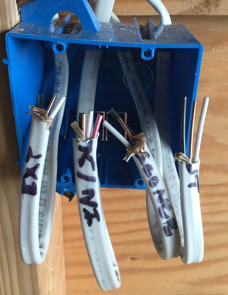
This all adds up. For example, in the gang box pictured below, there are three 14-gauge cables that each contain two conductors, one cable that contains three conductors, and two switches. So you have to add nine for the conductors, four for the switches, and one for the ground wires, for a total of 14. This box must be sized for at least fourteen 14-gauge conductors.

Wiring the lighting circuits
Lighting circuits are by far the hardest ones to wire. LEDs use very little power, so I only used two lighting circuits for the entire house. One powers the first-story lighting, and the other takes care of the second story.
There are multiple ways to wire lights, and I will go over several of them, but the important thing to keep in mind is that every light needs power from the panel, and every light needs to be wired to a switch. Sometimes it is easier to bring power to the switch, and then run a wire from the switch to the light. In this instance, the black wires go through the switch and the white, neutral wires are joined together in the box.
Alternatively, the power can be brought first to the light, and then to the switch. This gets just a little bit more complicated due to the wire coloring.
What about the ground wires? You must be wondering, if electricity doesn’t pass through those wires, why are they even there? This is a great question. Ground wires are only used in emergencies, and are part of the grounding system of the house to protect people from being shocked. Let’s say that somehow the “hot” wire comes loose or becomes corroded over time and comes into contact with part of the light fixture. That fixture is now electrically charged so if you touch it, you could get electrocuted.
Fortunately, the ground wire also is connected to the light fixture, and connected to the ground, so the current will flow through the ground wire to the ground. Building codes require the path of the grounding wires to encounter very little resistance; this low resistance will cause the current to spike and trip the breaker, cutting power off to the circuit.
You will need to use three-conductor cable when you connect a light to multiple switches. Three-way lights are required by building code over a stairway so you can operate the same light from either the top or the bottom of the stair. The third conductor is wired between the two switches so that the light can be powered through one conductor if both switches are up, or through the other conductor if both switches are down. If one switch is up and the other is down the circuit is disconnected and the light will not be lit.
In the master bedroom, the main light can be operated via a switch at the door, or via switches at either side of the bed. In effect, three different switches are capable of operating the same light! This is called a 4-way switch.
For light fixtures, you can use wall boxes for sconces or octagonal junction boxes for hanging fixtures. There are reinforced boxes you can use that are capable of handling heavy chandeliers as well. Just as with the gang boxes, it is important to do box-fill calculations to ensure that the box you are using has enough room for the number of conductors you wish to pass through it.
Securing wire and making up boxes
After all of the cables have been run between the main panel and the outlets, all the cables must be secured to the framing. The cable must be attached within 6 inches of an outlet and at least every 54 inches until they reach the main panel.
There are many products you can buy to secure the cable properly, but I went with the cheapest one and just used electrical staples. These allow you to staple two 2-conductor cables wires or one 3-conductor cable, and are very easily driven into the framing with a hammer. You must take care not to hammer them in so hard that they break the insulation on the wire.
On long raceways, it is important to separate the wires when possible to prevent them from overheating. In addition, wires can’t be stapled closer than 1 1/4 inch from the face of the framing. If cable goes through a hole that is closer than that, a metal plate must be attached to the framing to protect the cable from a nail or screw.
Once the wires are secured, it is time to make up the boxes. I used a sharp utility knife to cut a long slit in the sheathing on the Romex, exposing the conductors. If you cut the side that has the writing on it, the paper wrapping will be a lot easier to remove. It is important to cut the sheathing off at the very back of the box. Sometimes when there are multiple wires it helps to write which one is which on the nearest stud.
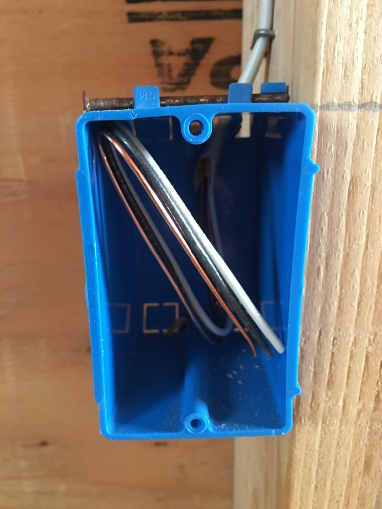
The easiest box to make up is a receptacle at the end of a circuit. You just strip the sheathing and paper away and leave the conductors and ground wire neatly folded near the front of the box, as the photo below shows.
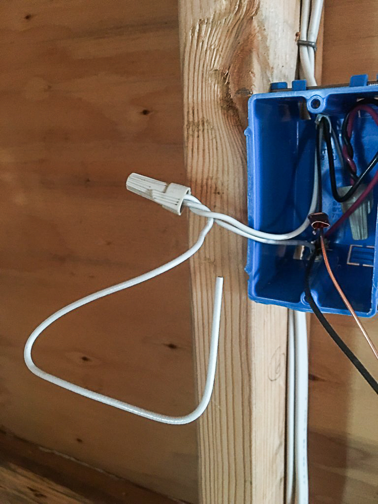
The next simplest is a switch at the end of the line. This is done just like the receptacle except you need to wrap black electrical tape over the white conductor to show that it is “hot.” I like to use some leftover Romex sheathing to mark that the outlet is a switch.
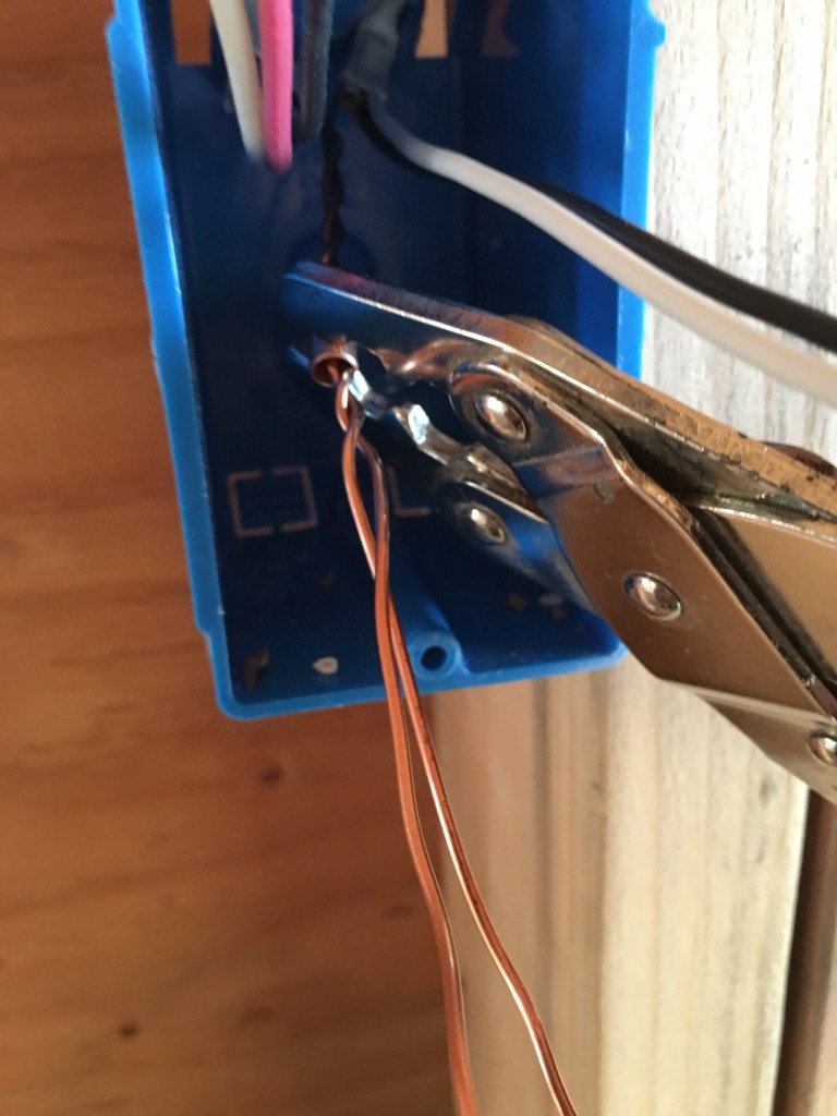
The remainder of the boxes will have more than one wire. It is easiest to start with the ground wires. If there are only two ground wires I twist them together six or seven times. Then I slide a crimp ring over them and use a pair of crimpers to pinch them tightly together, as the photo below shows. Next, I trim off any unnecessary ground wires (leave one remaining for each switch/receptacle in the box).
White conductors come next. If you are wiring a switch, make sure that none of them need to be taped to mark them as “hot.” This is usually due to power going to a light before the switch that controls it. If you mark a white conductor at one end, you must also mark it at the other end, at the box where the wire terminates. If you find yourself trying to connect a black conductor to a white conductor without an electrical device in between you will know right away you are doing something wrong.
The black and red conductors are the most difficult, and this is where it becomes very important to have written down which wires are which. Receptacles require one black conductor, while switches require two. Just as with the white conductors, if you have only two black conductors, you can attach both of them to a single receptacle.
For switches, one of the black conductors will need to be incoming power, and the other one will need to be going to the load. When there are multiple switches, you will need to use a pigtail. This time, instead of using a pigtail to turn multiple conductors into a single conductor, you will use the pigtail to turn a single wire coming from power into multiple wires that can each power a different switch. You may have power entering the box pigtailed to multiple switches, but you will also need to add to the pigtail other black conductors that will bring the power out of the box and into the next one.
It is really important that you pay attention to the packaging for the wire nuts you are using for your pigtails to ensure that it is the right size for the number of wires in the pigtail. Tan ones, for instance, can be used for between two and five 14-gauge conductors.
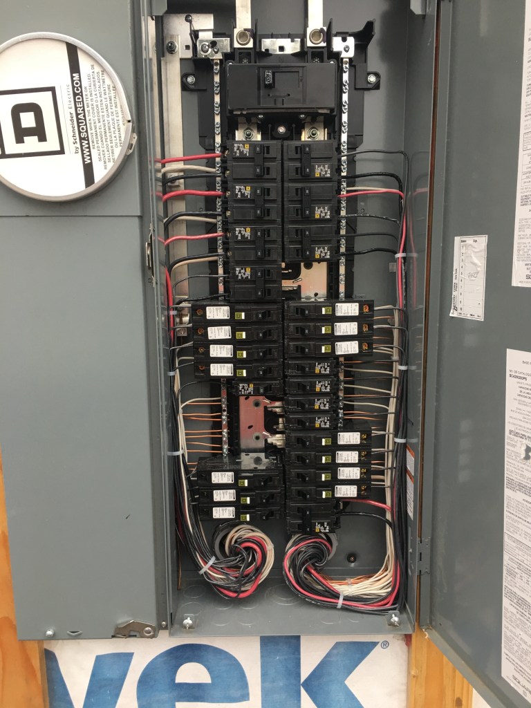
Wiring the panel
For some reason, I take immense pleasure in stripping wires and making them look good, so making up the main panel was a very enjoyable task. I spent a great deal of time making it look as clean as I could make it. At the end of the day, it really doesn’t matter as the number of people that will ever remove the “dead front” and look inside the panel is very limited. But building a house is much more rewarding if you take pride in the small things.
As I explained earlier, it is important to know the proper size circuit breaker for each individual circuit. Each circuit is built to power a “load,”whether it be a water heater or a refrigerator or a light. The proper size circuit breaker will know when the current increases above the planned maximum current for the load you have planned on the circuit and cut power.
The NEC requires that receptacles in garages, kitchens, bathrooms, outdoors, and laundry areas are protected by a special type of device called a ground fault circuit interrupter, or GFCI. This type of breaker will not only trip when the current rises above the maximum for the load, but also measures the current as it returns to the main panel to make sure that no current has “leaked” out of the system.
For example, let’s say someone is in the kitchen and doesn’t notice that the “hot” wire on the toaster cord has a puncture in it and is lying in a small puddle of water. When someone touches the water, they will be electrocuted. The current in the circuit won’t change significantly enough to trip the regular circuit breaker — it’s still powering a load. Unfortunately, that load would be a human being. The GFCI will trip in this case, however, because it senses that the power it is sending to the hot conductor is not returning to the main panel on the white neutral conductor.
Alternatively, instead of using a GFCI breaker, you can use a regular circuit breaker with a GFCI receptacle. This is what I will be doing as it is much more cost-effective, yet just as safe. You can connect multiple regular outlets downstream of a GFCI outlet and they will all have GFCI protection — provided it is wired correctly.
The last type of breaker is an arc fault circuit interrupter, or AFCI. These are required on almost all circuits that power multiple devices inside the house, other than bathrooms. If you have ever seen a spark plug work, you have seen an arc. Sometimes wires are just a little loose, so electricity can arc between them.
In this case, the load is still powered, so a regular breaker doesn’t detect anything amiss. The loss of power is so low that the GFCI breaker doesn’t detect it, and yet the spark is powerful enough to start a fire in the same way that the spark plugs in your car ignite the gasoline in your engine.
The AFCI has the ability to detect these arcs and will trip, alerting the homeowner to a potential problem in the wiring. I used a special AFCI breaker that is designed to connect not only to the main hot bus but also the neutral bus bar in the main panel. Again, the breakers work by monitoring the power as it returns to the panel and comparing it to the power that is leaving the panel.
Once the proper breakers are installed into the panel, it is just a simple process of stripping the wires and connecting them. The ground wires always go in any location on the neutral bar unless you are wiring a subpanel, in which case there must be a separate bar for the grounds that connects to a single ground wire that is wired directly to the main panel neutral bus bar.
White conductors also are connected to the neutral bar, unless they will be connected to a GFCI or AFCI breaker. The exception is when you have a 240-volt only circuit, in which case both the black and white conductors are hot and must be connected to the breaker. In this case, the white wire must be taped black to alert anyone operating on the panel that it is being used as a hot wire. The black and red conductors are always connected to the breakers.
Other blogs by Matt Bath:
Designing and Installing a Septic System
Weekly Newsletter
Get building science and energy efficiency advice, plus special offers, in your inbox.


86 Comments
That panel looks crazy to me, with all the wires coming in through two entry points. Is that the standard way of doing it in the US? Here in Canada, every cable has its own entry point into the box. Seems like bunching them all together like that could potentially produce a build-up of heat, not to mention the nightmare of trying to service one of those cables if it became necessary later on. Our NMD wire also doesn't have any paper in it.
You're a little off on your description of residential electricity. The two 120V "phases" don't cancel each other out, otherwise you'd have zero output. A better way of saying it is they sum together. But that's not exactly right either. There's actually only a single phase, 240V (nominal). You get two 120V circuits out of it by having a neutral that is half way between the two voltage potentials, kind of like the center tap of a transformer. That neutral is then tied to ground.
You used the term "electrocuted" a couple of times when you probably meant "shocked". You've only been electrocuted if you died.
Was thinking the same, Trevor! That panel looks like a nightmare!
I have purchased the panels and breakers for our build. One of the nice things about building our own place will be the ability to have extra circuits above what the code requires. No more will I have to plan for shutting down a large area when changing a simple receptacle.
We're building a two story house, so I planned a sub-panel for the second floor. We will have second floor laundry, so the savings of all that additional wire (and the labor to install it) not having to come from the main panel will pretty much offset the cost of the extra panel. It will be very convenient to not have to run back and forth to the basement, or shout back and forth from two floors away to confirm if I have the correct breaker switched off.
TIP: try to buy panels in "kits" that include breakers. The panel kits I bought each included six Combination Arc Fault Circuit Interrupters (AFCI) which are required on a lot of circuits in residences now. If purchased separately, the cost of those six breakers alone is almost as expensive as the whole panel kit including all the additional breakers it came with (18 in total).
" The two 120V "phases" don't cancel each other out, otherwise you'd have zero output. A better way of saying it is they sum together. But that's not exactly right either. "
yeah when I first read the 'cancels' out part I was scratching my head. I ended up taking it to mean return current on the grounded conductor can cancel (i.e. balancing loads, something not talked about, unless I missed it).
But I don't see it as an apt description of the relationship between the phases. "Summing together" seems better, but perhaps even better is to say it is simply the difference. This implies subtraction rather than addition, which gives us the results we need: 120 - -120= 120+120= 240
If you plotted it out over time, it would be the difference, but it would vary between 0V and +/-170V peak. If you're looking at the RMS voltage, neither one has a polarity, so it's not really accurate to think of one as +120V and the other -120V. They're both just 120Vrms, and together they are 240V.
I admit it may be overly simplistic. I'm not an EE... just an interested party member :)
RMS voltage by definition is plotted out over time, yes? I suppose I was thinking in averages. Is it true though, that the RMS cannot be considered positive for a period, then negative for a period (i.e. positive when above the x-axis and negative when below)? EDIT: I see that one cycle includes both portions, which is perhaps your point.
My understanding is that the sine waves are 180 degrees apart when measured to a neutral, and are a single (higher amplitude) sine wave when measured between the lines.
I agree that it's split phase, not 2 phase.
I also don't see a problem with the claim that the neutral is 'halfway between the two voltage potentials.' And we decide to ground at this point.
I do believe you are correct that a center tap on the transformer secondary is where we derive the third (grounded) conductor (the neutral). If we use a spring under tension as a metaphor: the ground is where we arbitrarily decide to latch on to the spring. From this point where we latch on, the other points will fly towards us when the tension is released. If we grab the middle, we'll have two ends flying at us with x potential each. If we grabbed one end, we'd have the opposite end coming at us with 2x potential. (rough analogy).
Trevor, you are talking way above your pay grade. The house is supplied with two 120V lines from the pole. Neutral to either provide 120V. They are out of phase with each other so voltage measured between the two 120V lines provides 240V. Single phase, 240V motors (and appliances) have two "out of phase" 120V supply lines, neutral, and ground.. Contrary to your other claim, that "You get two 120V circuits out of it by having a neutral that is halfway between the two voltage potentials" is nonsensical. You all should not make up non-electrical terms to describe or define Ohm's law.
Half of what you said is the equivalent of what I said. Ohms law, which describes the relationship between voltage, current and resistance, has nothing to do with anything being discussed, since we're only talking about one of those quantities. You seem to be arguing, although you didn't state it outright, that the power coming into the house is two-phase power (you have taken issue with me referring to it as single phase). I maintain that the power at the house is single phase power.
I suggest you read this:
https://en.wikipedia.org/wiki/Single-phase_electric_power
Here's the key bit:
"Single-phase is commonly divided in half at the distribution transformer on the secondary winding to create split-phase electric power for household appliances and lighting."
I will admit that I don't know exactly how they divide that voltage in half, which is why I simply stated that the neutral potential lies half way between the two split phase potentials. I didn't make up any terms. I think it's entirely possible that it's accomplished by center-tapping the transformer, but I don't know that for a fact, so I mentioned it as an analogy only.
Whether you are aware, or not, Ohm's Law is the basis for electrical theory., whether talking about, voltage, current, or watts. That aside, you don't have any background in electron flow so why are you discussing this? For your information, all conductors are single phase! A three-phase supply is made up of three single-phase wires, each out of phase with the other two. Voltage varies around the country tracing back to what Edison and others wired in their region. For three-phase, the voltage may be 220, 230, 240, 208, a multitude of voltages. Or double those voltages and reduce wire diameter. Only single-phase wires exist. Your home has two hot wires, both are nominally 120V. Again, a voltmeter across the two phases measures 240V. Voltage and current are inversely proportional. That's to say, double the available voltage from 120V to 240V and the current drops to half. Don't confuse single phase with three phase which can be three 240V lines and no neutral. A voltmeter across any two phases is 480V. Double the voltage and inversely, the current is halved, again Ohm's Law. The advantage of the higher voltage level is smaller wires and switchgear.
I realize we're approaching the splitting hairs stage here, and that this is a theoretical aside to a practical discussion... but just to point out, the original issue brought up by Trevor was, I believe, this phrase:
"The modern electrical service uses two nominal 120-volt “phases” of electricity that cancel each other out (nominal meaning they won’t actually be exactly 120 and will vary)."
Which, I agree, is confusing at best.
I'm curious why the notion: "You get two 120V circuits out of it by having a neutral that is halfway between the two voltage potentials" is nonsensical?
I might also point out that if we're talking about ohm's law, voltage is not inversely proportional to current. I=V/R. Doubling voltage will most certainly double current, not halve it. But I'm sure you mean that the same amount of power can be achieved with double the voltage and half the current (P=VI)
I think another point being made, pedantic as it may be, is that the two 'hot legs' on U.S. residential electrical systems don't constitute a two phase system (if each conductor is considered a single phase, we should not add these up and assume a two phase system). Split phase is generally accepted as more accurate.
Tyler, again, (and you said it yourself), the two 120V lines do not "cancel" each other). A neutral is just that, not a power line. If it were "halfway between the two power lines" then the voltage to ground would be 60V and vacillate as the sinusoidal waveform modulated with voltage changes each half cycle on each line. Between neutral and ground is 0V, Neutral is a non-conductor, meaning it's not one of the supply lines carrying power.
You are citing the basic Ohn's law. Formulas get complex and have to define the scenario to be valid. The application to a load is more complex than your basic expression. Look at any motor designed to run on two voltage levels. For example a 120/240V motor. Connect the wires one way and it functions on 120V. Wire another way and it will run equally on a 240V supply. Now, look at the plate on the motor. It shows the two voltages, 120 and 240 and it shows two currents. One amperage, for 120 V is half that stated amperage if run on 240V.
If running a heavy three-phase system especially, for example, running motors and all loads, on the higher voltage allows smaller conductors (wires...Ohm's law) because the current draw is cut in half simply because the voltage is doubled (current inversely proportional to voltage). It's quite a cost savings.
You can correctly call the two hot wire two phases. That's not to say the two phases constitutes a two-phase system. They do exist, oddly enough, but for most loads, in a home, only a single phase is used. But what about a water heater? The heater elements use both single phases to operate at 240V. Isn't that "two-phase"? Again, each phase is a "single phase, with a total of two, but it's not a two-phase system if only one line (phase) is used..
I cannot reply to your latest post Larry (perhaps the moderators want to see an end to this non-sense :)
One last. You do know that the 'two lines don't cancel' phrase is precisely the phrasing we took issue with? You seem to agree with that. So I'm not really sure what you are ultimately trying to point out.
I'm still not sure of the pointed relevance of Ohm's law in this context, but I think it's important to clarify that simply increasing voltage in a system does not decrease current, fundamentally. Try it with a light-bulb. Sure a motor with higher voltage can draw less current to do the same amount of work, but it's not really a complex formula: P=VI. I feel like the issue has gotten obfuscated.
I agree with your sentiments on the phases, and to be honest find it mostly semantics. We all agree its one phase coming off the power pole (for the situation we're discussing). Beyond that, I would simply consider how U.S. residential split phase power is derived from the transformer. The center tap (neutral) has 120 volts of potential to either hot leg (and the two hots have roughly 240 between 'em - no disagreement). It's simply the act of grounding the center tap that makes it have zero potential to ground. Many prefer to call this line the 'grounded conductor.' One could theoretically ground the outside of the winding (i.e. one of the lines currently treated as 'hot') and it would then have 0 voltage to ground, the center tap would have 120, and the opposite side of the winding would have 240.
I have worked as an electronics engineering technologist for 25 years. I am not an electrician, but I've studied AC theory.
I am familiar with Ohm's Law. It is not necessary to invoke it when discussing the phase relationship in an AC system, and in fact it adds nothing but distraction.
Conductors don't have a phase, they are just passive components that carry current.
You keep rambling on about things that have nothing to do with the topic.
"Again, a voltmeter across the two phases measures 240V." This is not in dispute, and has nothing to do with anything.
"Voltage and current are inversely proportional. That's to say, double the available voltage from 120V to 240V and the current drops to half." This is 100% wrong. I'm guessing you're trying to say that the amount of current you would need to produce the same power is halved, but that's very different from what you said. And it's also a non sequitur, i.e. it has nothing to do with what we're talking about.
"Don't confuse single phase with three phase which can be three 240V lines and no neutral. A voltmeter across any two phases is 480V. " Another non sequitur. I'm seeing a pattern here.
"Double the voltage and inversely, the current is halved, again Ohm's Law." Again, 100% wrong. Let's see what Ohm's Law actually has to say about this. 120V across 12 ohms produces 10A. Let's see if doubling the voltage to 240V halves, as you predict, the current to 5A. No, turns out it's 20A. And yes, I managed to infer what you might have actually meant, and allowing for that, it's still a non sequitur.
This is really getting tedious, so this will be my last reply.
"A neutral is just that, not a power line."
No one said it was.
"If it were "halfway between the two power lines" then the voltage to ground would be 60V and vacillate as the sinusoidal waveform modulated with voltage changes each half cycle on each line."
Utter nonsense. At any given point in the cycle, the halfway point is 0V. It's the reference at which you would measure the voltage on the other two lines, so by definition it's 0V. It's also bonded to ground. Have you ever seen a center tapped transformer? It perfectly illustrates how it works. You start out with a single phase, let's say 120V from the wall outlet. The output of the transformer has three wires, one at each end of the coil and one tapped at the middle. Set that center tap as the reference, and voila you have two equal voltages. You can get 2X voltage by connecting directly from end to end, or 1X voltage from either end to the center tap. Exactly what you have in your house, and it's still single phase. It comes from one coil.
"Between neutral and ground is 0V, Neutral is a non-conductor, meaning it's not one of the supply lines carrying power. "
Yes, ground and neutral are both 0V. That doesn't preclude the neutral from conducting current. And we all know that the neutral does carry current, it carries the unbalanced load. This is residential wiring 101.
"You are citing the basic Ohn's law. Formulas get complex and have to define the scenario to be valid."
YOU were the one who brought up Ohm's Law when it wasn't even necessary. We certainly don't need any more complex formulae. The rest of that paragraph is just another, long non sequitur. And so is the following paragraph.
"You can correctly call the two hot wire two phases."
This is the exact point we are arguing. You can't win the argument just by re-stating your position.
"That's not to say the two phases constitutes a two-phase system."
Really? I'd love to hear the logic behind that statement. On second thought, no, I wouldn't.
"But what about a water heater?"
Yeah, what about a water heater? I don't think you know how they work.
"The heater elements use both single phases to operate at 240V. Isn't that "two-phase"?"
Again, you'd tried to just assert the conclusion. There aren't two phases, so the water heater isn't using both. It's using 240V. Most water heaters don't even have a neutral line connection. I've actually never seen one that does have a neutral line connection. Some cooking ranges use 120V for electronics, and therefore need a neutral line. But water heaters have historically always run without a neutral line, so even ones with electronics these days that I've seen lack a neutral connection. Probably because it would hurt sales of retrofits for all the homes that have only a two conductor cable feeding their water heater.
"Again, each phase is a "single phase, with a total of two, but it's not a two-phase system if only one line (phase) is used.."
It's a system with two phases, but not a two phase system. Got it, makes PERFECT sense. The entire electrical industry is wrong when they call it single phase. And when a Master Electrician tells me that it's incorrect to refer to the two lines as two phases, I will give him your number so you can straighten him out.
Those AFCI's certainly have a place, but i think our code is way to stringent on them. I understand their use in places like bedrooms and living rooms where furniture can rest on a cord and possibly short the circuit, or a cord get jammed between a bedside table drawer, or even through a door.
However, places like a garage, where typical use of brushed motor power equipment is very likely, and equipment loads change very quickly from startup to idle to under load, I do not think they should be required. Several contractors were unable to cut their material in our garage with the arc fault breakers. They either had to move into the living space and create a dusty mess there, or *erm* find another solution....
Any breaker will trip on a short circuit condition. The AFCI is specifically designed to trip on an open circuit with arcing, which can lead to a fire.
As far as I know, there is no requirement for AFCI breakers in garages in the Ontario electric code. Maybe it's handled differently if the garage is attached?
AFCI suck in the real world, almost any brushed motor will trip them, even a shop vac..
From a safety perspective, I'd think you'd be just as likely if not more to have damage to cords in a garage when you're operating tools nearby and moving things around.
Maybe. But you're definitely far less likely to be asleep in the garage when a fire starts and burns it down. Which is why I think maybe if the garage is attached to the house, it might fall under the same rules as the house.
I did a little more digging. In the Canadian Electric Code, if the garage is attached, all the rules for the residence apply (therefore, AFCI breakers required). If it's an outbuilding, it's not part of the residence, so the same rules don't apply. I found several interpretations that state that no AFCIs are required in outbuildings as of the 2018 edition of the code.
Trevor,
I think that's a general rule that applies to building code requirements too. An attached garage is considered as part of the house. The only exception I can think of is that the wall between the garage and house is still considered an external one for the purposes of insulation, vapour barriers and air-sealing.
Matt, the panel organization is great--I'll take that any day over what I have in my present project. Tightly bundling wires is a concern, though. Behind there, I'm guessing they are passing through short sections of 2.5" conduit? My understanding is that conduit can't be more than 60% full, but I imagine there are rules and conditions about that. Photo suggests you're probably OK on this.
And while we're nitpicking, the neutral/ground thing is a matter of great confusion. You say, "The ground wires always go in any location on the neutral bar unless you are wiring a subpanel, in which case there must be a separate bar for the grounds that connects to a single ground wire that is wired directly to the main panel neutral bus bar." In my jurisdiction, neutral and ground must be bonded in one place only--the meter base. Thereafter, particularly in the main panel, the neutral bus (and all the white wires) must have no connection with the ground bus (and all the bare wires). Looks like your meter base is immediately adjacent, so perhaps bonding in the main panel is kosher. Rules vary for how subpanels must have their own grounding scheme.
Overall, I'm guessing you had this thing inspected, so if the AHJ is happy, we're all happy!
Not an electrician, but as a homeowner who's done some major remodeling myself, here are some of my observations on things that have made electrical work better / easier:
Commercial / spec grade outlets and switches
- The higher grade receptacles usually allow for back-wiring, where you just strip the wire, insert, & screw down a clamp. Much quicker and easier than trying to wrap wires around a screw (note that this is not to be confused with "back-stab" systems where you just push in a wire and it has a friction fit inside the outlet)
- The plugs on higher grade outlets usually hold cords better and the tamper resistant mechanisms just seem to work better
- Have you ever noticed how you sometimes can hear a sparking / crackling sound if you move a cheap switch slowly between off / on? Doesn't happen with the higher grade switches.
Here's a good comparison of some different grade outlets and the differences in how they can be connected:
https://www.handymanhowto.com/electrical-outlets-side-wire-versus-back-wire/
Wago Lever-Nuts
- Uses separate levers to clamp down on each incoming wire
- Much, much, much less headache than working with traditional wire nuts.
- Faster and easier than the twist & crimp method for ground wires
- When you have a larger number of wires, they seem to hold everything together more securely (they have support for 2, 3, or 5 wires)
- Also far easier to add things later
https://www.wago.com/221/us/
Grounding pigtails
- Again, another shortcut that can save you from having to try to bend wires around screws on plugs
- With the lever-nuts, I usually buy the double ended type and just cut them in half, putting the cut / stripped end into the lever nut and screwing the other end down to the receptacle
12G wiring for anything with plugs or where you might add on later
- The cost is minimal vs. the cost & effort of trying to replace wiring or determine what was used throughout a run later
- You can still use 15A plugs for lower cost, even on a 20A circuit (the only time you'd need a "20A plug" is if you're planning on plugging in a single appliance capable of drawing 20A that has the different style plug)
- You can even use cheaper 15A breakers if you don't expect the load to be higher now
Pay a little more for better staples
- The type with 2 nails & a plastic bridge are less likely to damage cables and are far easier to remove if you need to take them out later
- If you're running a lot of wires and are concerned about heat, many of the more expensive types are designed to maintain some spacing between the wires to help prevent overheating
Use fan-mount boxes for all ceiling fixtures where it might be possible that someone would want one
- Even if you're not installing a fan now, it gives flexibility later
Standardize on running 3 wires from switches to lights
- Having the incoming wiring at the switch guarantees that you'll have all 3 conductors at the switch (hot / neutral / ground), which is often needed if you want to put in dimmers or other more complicated controls later
- Having the 3rd wire in the run to the light ensures that you can use separate controls for fan / light later if you decide to install a fan
Use bigger boxes
- It's almost always easier to fit things in a 2 gang box than it is a 1 gang box
- For light switches, it gives you the flexibility to add a separate switch for a fan later
- For outlets, having 4 plugs instead of 2 can often save you from needing to use a power strip later on
- For old work boxes, the cutout for a 2 gang box is far easier to reach into to fish wire than a 1 gang box
Don't be afraid of "empty" boxes
- With some planning, star topology / hub & spoke wiring can simplify outlets and require less overall cable to run
- Just use a a single box with 1 incoming wire, multiple wires out, & a blank cover plate
Consider going above code on your smoke detector circuit
- Heat alarms in the garage & near the furnace / hot water heater can add extra protection
- Wiring up an a second box in each room allows you the flexibility to add a flashing strobe later
Invest in better boxes
- I've found I'd much rather use a screw-in box than a nail-in box -- far less opportunity to damage the box on accident while installing
- If you're working with old work boxes, the type with metal tabs that pull close always tighten up much more smoothly than the type with the blue plastic tabs
Leave yourself notes at each outlet
- The more you write down, the better off you'll be if you ever need to work on the wiring again
- Mark the circuit breaker # in the box (or on the back of the outlet cover) -- no more guessing game flipping breakers to figure out which needs to be turned off to cut power
- For boxes with multiple wires, leave yourself an arrow or note to indicate which is the incoming wire
- Leave a note to indicate where each of the outgoing wires is headed
Take photos of everything before you seal up the walls
- Rather than relying on a stud finder to figure things out later, it's always better to have a set of reference photos that you can easily browse through later
Leave at least 2 breakers open on each side at the top of the breaker box
- Many Type 2 whole home surge protectors require being placed in the first 2 circuits in the box. If think there's any chance that you might add one later, it's a lot easier to just leave space at the top when you're initially wiring things up.
Consider AV when planning circuits
- If you're going to have an AV receiver, TV (or projector), and / or powered subwoofers, keep them all on the same circuit -- having equipment on separate circuits can introduce a ground loop (devices have more than 1 path to ground via AV cables and it results in an annoying buzz/hum)
Consider dedicated circuits for vacuuming
- Vacuums (especially older ones) are electrically somewhat noisy and can be prone to tripping AFCI breakers
- Having them on their own circuit breaker means less likelihood of losing power to sensitive electronics or other things if it trips
Consider a dedicated 20A circuit & plug for space heaters
- If you plan on using space heaters, consider putting a dedicated 20A circuit & plug just for that in each room where you think they'd be used
- An 1800W space heater puts a 15A outlet pretty much at capacity -- with anything else plugged in on the circuit, it's likely to trip
Consider outlet positioning for nightlights
- We use amber led nightlights throughout our house to avoid needing to turn on lights at night whenever possible (in addition to the cost of turning on primary lighting, exposure to blue light interferes with sleep).
- A single nightlight in each bathroom positioned so that it can illuminate both sink & a toilet with someone standing in front (usually requires an outlet in a higher than usual position)
- A nightlight at the middle of each staircase
To pick up on some of the very good suggestions Timothy made:
- Leave a courtesy loop between the last staple and the box so you always have more wire to pull if the wires in the box get damaged.
- The suggestion that each box with a switch should have a neutral available I think is now enshrined in most electrical codes.
- Consider using Leviton's new control centre. It has a hot bar as well as those for neutrals and grounds. Makes changing circuit breakers a lot easier. It also looks a lot better than most if it is going to be located somewhere it can be seen. https://www.leviton.com/standalone/LoadCenter/assets/doc/Load-Center_Brochure.pdf
One more note on box fill: If the box has integrated clamps, like your multi-gang boxes appear to, you have to subtract one more conductor count for that.
New construction single gang boxes often omit clamps, and the code allows this, as long as you staple the cable within 8 inches of the box (instead of the usual 12).
Just out of curiosity, what are the manufacturers of some of the screw-in and air tight electrical boxes that you guys use? Thanks!
Funny you ask. I've been surveying all of the screw-in boxes available lately. There are four competing models:
Arlington F101
Madison MSB22+
Allied SB-1
Carlon B125AB
All but the Arlington have internal clamps, so those need the deduction I mentioned in my previous comment. The Arlington has circular knockouts and comes with romex clamps that can be installed such that the clamp is outside the box and does not require a deduction. However, it has a slightly lower capacity anyway, so this doesn't really yield a higher capacity. The end result is that, after deducting the necessary clamp allowance from them, as well as the usual device and ground deductions, they will all fit 6 12 gauge conductors. If you're using 14 gauge conductors, then the Arlington and Carlon have a slight edge at 8 conductors, vs. 7 for the Madison and Allied.
There's also the smaller Madison MSB1G which is otherwise the same as its larger sibling. It's a bit shallower, so maybe useful on exterior walls where you want to reduce the thermal defect in the wall.
Another thing to note is that the Carlon box doesn't come with screws supplied, although I think it's cheaper to compensate.
Another option for old work is the Carlon B117RSWR shallow old work box. It's thermally preferable to have a shallow, wide box, rather than the usual deep, skinny box. But its capacity is lower, and I don't think there's any way to use it in the usual new construction inspection process that requires boxes be up before drywall.
All of these boxes need sealing for air tightness.
The Carlon FN-18 and FN-23 "draft tight" boxes are also worth consideration, although personally I am trying to avoid mounting boxes to my plaster, so I ruled them out.
For basic screw-in boxes (not air-tight), I like the Legrand boxes (Menards carries them around here)
I would like to see more information on where you decided to install lighting throughout the house and the types of fixtures you chose. I realize your plan drawing is a general layout but how did you decide on the number and precise placement of the fixtures?
For example, in the kitchen it seems that there are no upper cabinets along the exterior stove wall and all the lights are ceiling fixtures running across the center of the room. This will cast dark shadows on the countertops while you're doing prep work and cooking. Perhaps pin lights centered over the countertops and if you have upper cabinets on the opposite wall where the sink is some under cabinet lights?
Also, I'm curious about how you managed to have only a spiral staircase to access the second floor? Don't codes require a straight stair in case fire fighters have to get upstairs?
This looks like it will be a dark house to me. I count 16 light fixtures on that floor, excluding outdoors and in closets. This kind of layout seems like what was typical in the 1980s and eariler. My house has 55 light fixtures on the main floor, and we don't regret any of them. Dimmers make it pretty easy to modulate the amount of light as desired.
Another experienced amateur here. I suggest using Buchanan wire crimps for bonding. Inspectors love them. They know that it will be harder for future diddlers to mess up the bonding system, and when they see the distinctive dimples from the Buchanan crimp tool they assume that they are dealing with a homeowner who knows what's what. They also take up less space than a green wire nut.
If I were in need of airtight electrical boxes I'd use Airfoil boxes. Besides a generous flange they have a little chamber that the wires pass through. You foam the chambers from the front creating an airtight wire entrance.
http://www.airfoilinc.com/products/products.html
Douglas Higden
If you ask inspectors what they like to see when they look at wiring, it's that they can't tell it was done by an owner. The closer you can mimic the work of a ticketed electrician in both execution and materials, the happier they are. I'm not sure searching for exotic, "better" materials or ways to do things is as useful as learning the proper commonly accepted way to rough-in a house and doing that to the best of your ability.
I think depending on electrical rough in for the airtightness of your house is a bad approach overall. Anything you can do in the planning stage to avoid additional air sealing and detailing by the trades is a step in the right direction. I'm sure many electricians take great pride in their work, but I doubt many of them are really "into" air sealing, or take the energy efficiency of your envelope to heart. Things that are not considered enjoyable are rarely things that get done well.
I agree. The building assemblies should have an air-sealing strategy to incorporate the electrical service that needs to be installed - without relying on the electrician's work. Sure they should use gasketted boxes if requested, and not drill holes though things you don't want them to, but beyond that it isn't their job to air-seal a house.
People often criticize based on their own experience. One person may think that depending on an air tight electrical installation is a waste of time and the air barrier should be another place in the wall assembly, but if you are retrofitting a house with perfectly good exterior and interior finishes, making the electrical boxes airtight is fundamental.
If you’re retrofitting or just trying to improve an existing house with leaky receptacles in exterior walls, of course you have to work with what’s there.
I was hoping my comment would be read with regards to planning a new build. I was not suggesting that air sealing work on an existing house was not worth the effort.
Has anyone ever heard the phrase "the saddest thing in the world is to spend your entire life climbing the ladder of success only to find out it's leaning against the wrong wall"?
Well for me, there's no point in doing the best possible installation of wiring, panels and boxes (all to code) and with top quality products if the fixture is in the wrong spot. Lot's of discussion on "how" to install the lighting, not much on "where". Until you know "where", don't start.
Scott,
This is kind of a "how" site. That's sort of the mandate.
Discussion of "what goes where" is pretty common here for windows, doesn't seem like it would be much different for lights.
For things like lighting, part of the "how" for green building is figuring out an effective layout for lights that balances output vs. watts used.
In the same room, I could place a single fixture with two 10-watt / 1200 lumen LED bulbs or 3 fixtures with a single 6-watt / 800 lumen bulb in each spread throughout the room. The raw lumen output might be slightly lower with the 3 light combination, but with the light sources spread more evenly throughout the room it may appear brighter with a lower cost to operate.
Lighting typically goes on the ceiling. You're welcome. :-)
Lighting typically goes on the ceiling...even though most of the time general lighting should point AT the ceiling...
That's a matter of opinion. I understand the concept of indirect lighting, but it comes with its own drawbacks. In larger rooms, it's pretty challenging to get that indirect lighting in a way that will agree with most peoples' tastes. Diffusing the light accomplishes the same thing. What I don't agree with is the idea that shining a light at the ceiling more accurately simulates natural light. It may more closely replicate the effect of natural light coming into a house through windows, but if you go outside, the light is coming at from above and it's a perfectly pleasant experience. The "shadows on the floor" argument can also be addressed by the proper spacing of overhead lights.
The difference in intensity of the transition from the downlighting fixture to the background matters. A high contrast with a bright center/dim field causes mammalian eye pupils to constrict, and needs more lumens to achieve the same visual acuity as a neutral-density even field of light from above. In the lighting definition world this is the definition of "glare".
Putting a diffuser on the downlighting reduces the glare somewhat, but it's not the same as uplighting.
Adding uplighting to light up the field surrounding the downlighting combined with lowering the intensity of the downlights reduces glare. Put them both on dimmers and the lighting conditions can be tuned for changes in task/use or personal preference.
There's an article for that: https://www.greenbuildingadvisor.com/article/martins-10-rules-of-lighting
So much good practical info in the article and comments.
"Fortunately, the ground wire also is connected to the light fixture, and connected to the ground, so the [fault] current will flow through the ground wire to the ground. Building codes require the path of the grounding wires to encounter very little resistance; this low resistance will cause the current to spike and trip the breaker, cutting power off to the circuit."
While the last sentence sort of implies this, it may be worth noting that while the ground wires (aka. equipment grounding conductors) are near ground potential, the actual fault current path (low resistance path) that trips the breaker is not really 'to the ground' but rather through the ground/neutral bond and back to the transformer via the service entrance. Minor, and moot if one simply follows the code, but never hurts to understand it and be clear about it. May be especially relevant if someone is dealing with a sub-panel that has its own ground rod (certain special cases) and erroneously believes that the ground rod will be their effective fault path protection in lieu of a continuous grounding conductor all the way to the transformer.
I'm a fan of indirect lighting but the downside is low light levels and little drama. Downlight has intensity and drama but the ceiling and upper walls are dark, and to me make the room dreary. If you put downlights near the room corners they will reflect off the neighboring walls giving a balance of direct and reflected light. Another solution is to use sconces that have open tops and diffusing sides. They provide good proportion of reflected ceiling light. Funnily, a good balanced light is the old fashion surface light with suspended glass diffuser. Most of the light spills out the sides and is reflected from the ceiling.
In another thread people gave advice about how one should prewire for cable, internet, etc. Houses last a long time but many technologies come and go, and most of those that require wire interconnection are going permanently. It's cute to see an early 20th century house with an elaborate telephone niche. On a This Old House episode the electrician pointed out an electrical outlet that included two binding posts that connects to a long wire dipole antenna meant for a console AM radio. I'm wondering when hard wired light switches will disappear. Lights will be wired in strings like outlets. Smart lights will be used. They can be operated by phone, computer or voice. If you want physical switches you just paste one on the wall and tell it what light(s) it will control. Want the switch in a different place? Just move it. Think of the burden lifted form designers, electricians and copper supplies.
That would be great - and it's probably coming quite quickly. I wonder what the standby loses would be for all those devices and fixtures sitting waiting for a command?
I suspect the standby losses will be low, but you could install fixtures with pull string switches.
Timothy makes a good point in comment #27 in which he says: "Discussion of "what goes where" is pretty common here for windows, doesn't seem like it would be much different for lights" although he approaches it from the perspective of "an effective layout for lights that balances output vs. watts used".
Yes, the overall power usage of your lighting system is important to know. Everyone wants an effective, low cost system to install and operate whether it's electrical or plumbing or HVAC. However, the best thing to do first is to properly place the lighting system.
Now, I don't know if the lighting diagram included with this article is a true representation of the authors build or whether he just copied a generic lighting plan off of Google images but it's not laid out very well.
Yes, "lighting usually goes on the ceiling" but if all your kitchen fixtures are mounted on the ceiling in the middle of the room you'll get shadows across the countertops whenever you're standing there prepping food, cooking or doing the dishes. It may not bother you but your wife will definitely notice.
Also, why are there two pot lights shining down onto the tops of peoples heads in the dining booth area, another two pot lights at the outer table corners and yet another light in the center of the table? Some of those pot lights would be better used in the entrance area.
All I'm saying is if you're going to invest the time and energy to research every little detail on how to correctly install your lighting system you should spend just as much time on where to install it. If you analyze your layout to see where you actually need the light and then install the fixtures in those locations you'll naturally have a system that balances output vs watts used.
Scott,
I didn't mean to imply design wasn't important - that's what I do for a living. It's just that the emphasis and expertise on GBA is typically oriented towards the meat and potatoes of construction, concentrating on the energy implications of certain strategies and building assemblies. We could easily spend as much time on the architectural design of each of the poster's houses, but that doesn't play to the strength of the site. In a similar way, I wouldn't post details of my foundation on Houz.
Trevor, agreed, "increasing V in a lightbulb does not increase A. Likewise for a motor. I never said that. I said the relationship between Voltage and amperage is inversely proportional. Think about this, Why do companies prefer to operate their equipment on higher voltage if it also increased the current for the same HP, heat, or light? They don't. A motor wired to run on 240V will draw half the current as the same motor/HP wired for 240V.
Trevor, I'm not sure what weight to give to your "credentials." My degree is in robotics, I taught electrical & electronics to engineers & technicians. I've designed & patented electronic/electro-magnetic switchgear. I've written several training manuals on programmable controllers, industrial motor controls, industrial electronics, hydraulics, etc. During the late 1980s when Mitsubitsi was banned from selling electronic components I modified their servo motor circuit boards to operate using a much different SCR & TRIAC. That allowed American machine tools to keep running. I can't make you guys accept the physics of what I shared so please continue with your opinions. Oh, when I mention Ohm's law or some other point, it's relevant. Please, pretend to discuss whatever you wish. I don't need to intervene. The physics of electron flow is whatever you misunderstand it to be. My technicians are always much better trained.
Trevor, If I was guessing, I'd conclude you googled my comments, and are replying with the results of your search. Each of your posts further dilutes the topic, level of discussion, and knowledge. Being right is your goal. Your bruised ego is clouding your intellect. I've taught both single & three phase, working with as-high-as 6,300 volts three-phase powering 1,500 HP motors. I don't recall anyone ever accusing me of confusing that power with house wiring. I wore protective arc flash gear. As a side note, I once tutored an EE for eight hours so she could testify in court as an "expert witness." You've been a technician for 25 years because your skill, training, and experience is limited.
How is the neutral "halfway between the two conductors? Is that something you made up? You were talking about voltage levels...half way is 60. I'm trying to make sense of what you claim.
There are many transformer configurations, used on both single & triple-phase. No one is talking about "Transformers"..
Agreed, I pointed out you were not understanding V&A are inversely proportional. I get it, you don't have the background, but that doesn't dismiss the physics, just your knowledge level. I don't have "logic" for you Trevor, just physics. If you don't understand I can't fix that. continue your training.
All water heaters are single phase. some have one hot wire, some two, and some three. Ever heard of "balancing a heater system"...so each phase carries (draws) the same current? Agreed, a residential water heater does not use a neutral. But that is likely to change. Where do you suppose the 240 V WH gets the voltage? Wouldn't that be from two single lines? Those lines are out of phase with each other.
No, I wasn't asserting an answer...I was asking a question and trying to drop a hint...connect the dots...very closely. I failed.
Trevor, you said, "There aren't two phases, so the water heater isn't using both. It's using 240V."
Trevor, you need to LISTEN and learn the basics. Where do you suppose the 240V comes from? Residential wiring doesn't have 240V in the USA. Residential wiring has a neutral, a ground, and two 120V supply lines. The power for those two lines are made using different generators and are set to be "out of phase with each other. If they were the same phase your meter would read zero across them. Instead, your meter reads 240V. If you can't understand that then stop embarrassing yourself and wasting my time. I'm going for a bike ride. Think a little and stop trying to be right.
While perhaps interesting, I'm struggling to see why understanding what happens beyond the panel matters in any practical way. There are all sorts of things like this in building that you don't really need to know. Things that are exclusively the domain of another profession, like most engineering, or that occur outside the scope of what you are working on, and to me that is the case in the discussion here. Probably more important is to know your limits. Most builders can do the basic wiring to add a circuit to a panel. Some like Matt have enough knowledge to wire an entire house. Neither of them need more theoretical knowledge unless they are going to stray beyond the scope of their understanding. What is a lot more useful is mastering the skills necessary for the task they are doing.
"While perhaps interesting, I'm struggling to see why understanding what happens beyond the panel matters in any practical way."
Malcolm, I agree with you, especially given the purpose of this forum (its not an engineering forum), however two caveats.
1) I never think its a bad idea to correct a notion that is, at best, misleading, and at worst, wrong and dangerous to have. I didn't anticipate the wormhole that followed to ensue.
2) Unfortunately the wormhole that did ensue came with a boat load more misconceptions and falsehoods from Larry. I can't seem to address him directly, as my responses apparently go in one 'ear' and out the other. Doubly unfortunate is that someone reading those responses who doesn't know better and is impressionable is getting false information.
In the end, I agree it doesn't seem to be worth having a back and fourth, because the waters have been unduly muddied and the lens is apparently opaque. I would encourage anyone following the discourse between Larry, Trevor, and myself to look into the subject on their own if they are interested in it, and to come to their own conclusions. What Larry is engaging in feels an awful lot like gas-lighting to me. Someone with a good head on their shoulders and enough time will come to the needed conclusions. I dare say any good electrician, no less electrical engineer, will see the insanity in his posts.
I mean this right here: "Residential wiring doesn't have 240V in the USA." - Larry
I won't bother picking apart the rest.
Larry wrote:
"Double the voltage and inversely, the current is halved, again Ohm's Law."
For a given electrical circuit, that is incorrect. If he had instead stated that, for a GIVEN POWER LEVEL, doubling the voltage reduces the required current by half, he'd have been correct. But that's not what he wrote, what he wrote was wrong.
He's aggressively entered into a conversation looking for a fight with people who obviously know how electricity works, attempting to beat them over the head with kindergarten level electrical theory and insulting their level of knowledge and education. And for no apparent reason other than to pick on semantics and try to prove someone wrong. Sad.
Tyler,
Larry does have a history of being a bit disruptive here...
Lance, I don't need the cut n paste version. The others didn't have a clue and your comment is after the fact. The only thing "obvious is you are late to the party. So next time weigh in with your cut n paste a little earlier and see if it helps. At least you verify the facts. I see nothing suggesting your friend knows electricity. In fact, he claims not to, even stating he's an "electronics technician." Again, it's admirable you are concerned about his self-esteem. He'll recover, and perhaps be a little wiser? Maybe you could use his expertise where you work...a job & and; raise? That's what real buddies do.
Malcolm, not "just here", I am "disruptive," as you characterize my presence, wherever I witness ignorance, the blind leading the blind, an author bs'ing in his article, anywhere a different perspective might keep easily influenced folks from being misled.
My impression is I added to the conversation and ignorance reared it's ugly head. I can teach a class anywhere in the USA and am accepted as an "expert." In cyberspace, the feeble-minded come out from under their rocks to argue. And supporters try to ease their pain. I made my point about the relationship between V&A. It's not important to me some tech with 35 years on the job refuses to grow.
Larry, you said:
"I can teach a class anywhere in the USA and am excepted as an "expert." "
ex·cept·ed
Definition: not included in the category or group specified.
Again, sad... this time you said it yourself.
larry,
I'm torn about responding because, like the rest of the discussion, I'm not sure continuing this has any positive value. But I'd urge you to look back at your contribution to this thread, and whether it couldn't have been lot more useful if you hadn't framed everything in such an insulting way. Positioning yourself as the One Just Man rarely helps people to see your point of view. Anyway, I'm sure you have other fields to plow, other ignorant fools to correct. Good luck!
It's good to know that Larry doesn't restrict his trolling to just one site. I honestly wonder whether he's managed to get a single person to agree with him. That should probably be a hint that maybe he's not quite the expert he thinks he is on every subject with which he asserts his authority. I don't believe for one second that he teaches classes in anything and is seen as an expert. Subject matter aside, the attitude alone would result in someone bashing his head in. I didn't recognize the name from a previous encounter, otherwise I wouldn't have even replied the first time. I think there's some mental health issues at play here.
I told myself I would leave this alone, but Larry's latest responses get to the heart of it: He can't make a case using logic, he is simply trying to convince others here that 'he is the smart one. He is the right one.' This is a classic logic fallacy. I don't care what credentials Larry has (if he really has them) if he can't make sense of a basic conversation concerning residential electrical delivery. I use the word conversation intentionally, because electric theory aside, it doesn't seem he can follow what is being talked about.
A discerning reader that took the time to actually read through the relevant posts will see that he's even quoted things that no-one even said (and implied things were said that were not). Straw-man much?
Calling Lance's post 'cut n paste' does nothing to address the issues.
I think we all agree that for a given Power, increasing voltage decreases required current. This is the inverse relationship Larry is, for some reason, trying to drive home. No-one ever disagreed. Saying current and voltage have an inverse relationship on its own is incorrect. In regards to a constant resistance it is very much not the case. (see what happens if you hook an old light-bulb up to the two hots- measure the current draw, voltage, even resistance if you want).
Furthermore, this ohms law malarkey is a distraction and has little specific relevance to the issue of voltage and phases. Despite what he says, it has MUCH to do with transformers, as this is where the high voltage from the power company is 'stepped down' to lower voltage. From one end of the secondary coil to the other, is (roughly) 240 volts. Positioned in the middle of that winding is our 'neutral' (or grounded conductor). This has zero volts to ground (because we ground it) and 120 volts to each side of the winding.
"Residential wiring has a neutral, a ground, and two 120V supply lines. The power for those two lines are made using different generators and are set to be "out of phase with each other. " -Larry
^ One of several statements that are flat out and verifiably wrong. You honestly think the power is coming from two different generators set to different phases?
"Those lines are out of phase with each other." -Larry
Assuming we're still talking about split phase U.S. Residential: In reference to the neutral, you could say that, yes, they are 180 out of phase. To each other, they are in phase, and would produce a single sine wave if one could do so on an oscilloscope without blowing it. The heart of what most people mean by '2-phase' system is that the sine waves are 120 degrees out of phase with each other (yet there is no third, as in a 3 phase). Different from a split, single phase.
Honestly the phase business is complicated, and is the least of our worries if we're operating with some of the notions purported (that the system does not have 240 volts?). It appears a basic grasp on voltage and that it is the 'potential difference' of electric charge 'between two points' is not had.
I don't say this to be rude. I don't know Larry as a person. Maybe I could enjoy a bear, in proximity to him. His presence in this discussion has been toxic, however.
edit: is he laughing his **s off right now, having a good ol time trolling? Is that what's going on? Darn internet. Buenos noches.
This may be what happens when the density of knowledge in one's head is so great, the resulting gravitational pull keeps anything, even knowledge itself, from escaping. Getting close enough to have a beer with such an individual would put you at risk of being pulled in.
"Assuming we're still talking about split phase U.S. Residential: In reference to the neutral, you could say that, yes, they are 180 out of phase. To each other, they are in phase, and would produce a single sine wave if one could do so on an oscilloscope without blowing it"
I'm sorry but this is wrong, otherwise the resulting voltage L2 (+120 RMS) - L1 (-120 RMS) would be a DC voltage always equals to OV.. A split phase means that you produce two phases (180 degrees apart) from a single input phase by using a center tap transformer. See this picture :
In case anyone's not familiar with the schematic of a center tap transformer, it looks like this:
Alex,
These are the semantics that I agree are maybe best to avoid and are beyond the scope here. For my part, I should not have brought it up in my last post. The main, and original issue, was not about this (or didn't need to be necessarily. I saw it more of a discussion on line voltages). This is rather complex and has a lot to do with how one phrases, and measures things.
I admit I may have phrased things inappropriately (concerning phases ;) I certainly shouldn't have brought up an oscilloscope. If you look at what I wrote, I did say that when measured, as it usually would be with a scope, it would produce exactly the graph you posted.
But I stand by the notion that the phase of the secondary coil is a single phase in its entirety (it is a de-amplified mirror of the single phase of the primary). Any voltage is always in-phase with itself. This, most importantly, being typical U.S. residential, single phase delivery (it's different in different places).
Edit: If there is any shred of relevance to this article, at this point, in my opinion it would be concerning the transformer, how the power is derived, how it's grounded, and what the voltages are between points. The phases may be somewhat useful in understanding that two equal loads derived from opposite 'hot legs' will balance and 'cancel' return current on the neutral (This probably being the intended meaning of the article author's statement about the lines 'cancelling.')
Just a bread crumb:
This comes from 'all about circuits .com'
The accompanying text:
"Split phase 120/240 Vac source is equivalent to two series aiding 120 Vac sources."
So to clarify, the two voltage sources it's showing are to represent an equivalence, not to suggest that there are two AC generators hanging up on our utility poles.
note: be sure to click on the image to see its entirety, otherwise it won't make sense.
This has a pretty good laymen's explanation of split-phase power. I wish I'd googled it earlier. As I suspected, the neutral is achieved with a run of the mill center tapped transformer.
https://en.wikipedia.org/wiki/Split-phase_electric_power
This is the key bit that explains the technical difference between split phase and two phase:
"Since the two phasors do not define a unique direction of rotation for a revolving magnetic field, a split single-phase is not a two-phase system. "
Alex,
I agree that the phrase "to each other, they are in phase" is wrong and I'm not quite sure what was meant by it. If they are in phase "to each other", they are in phase, period. So I'm not sure what you interpreted it to mean when you say that it would result in 340VDC. If you had two AC signals that are independent (i.e. they each have two terminals), you have two ways of connecting them: series or parallel. If you hook them up in parallel, they neither add nor subtract, they just overlap (any amplitude difference will result in one supply sinking current from the other until they are equal - this could be a bad thing). If you hook them up in series, then by definition you've made them 180deg out of phase, and they add. Note this is all hypothetical, I'm not suggesting this is a way to handle AC power. In the case of split phase residential, what you effectively have is two 120V supplies that have been connected in series, although it's arrived at the opposite way - a single supply center tapped to give two. No configuration of AC signals or phase angles is going to produce a DC voltage, excepting if you consider the neutral in a central tapped system which is 0V. You need rectifiers to convert it to DC. A full wave rectification of 240VAC will result in (slightly under) 340VDC.
Tyler is correct that the waveform between L1 and L2 is a single sine wave, with a peak to peak amplitude of 680V (nominal). You actually can measure it, you just need an non-grounded scope (and high voltage probes).
Hello Trevor
You are confusing some things here. A voltage is defined by the difference between TWO signal potentials not just one signal. You must define what are the reference points in your circuit before talking about a voltage source, otherwise it doesn't make any sense. In a residential circuit, you only have one voltage source. If it's a 120v circuit, the voltage is the difference between the +120V leg and the neutral. If it's a 240v circuit, it's the difference between the +120V leg and the -120V leg. There are no other voltage source. Since there is only one voltage source, there is no such thing as signals in parallels or series.
Let's put this in math. An AC signal is defined by the following equation :
V= DC voltage + AC voltage = DC + sin(wt + phase)
If you are measuring the voltage between these two signals and they are in phase, you will have :
A=DC1 + sin(wt + phase) (V)
B= DC2 + sin(wt + phase) (V)
C = A - B = DC1 + sin(wt + phase1) - DC2 - sin(wt + phase2)
where C is the voltage difference between the two signals. Now if phase1 = phase2 as you said, you would have C = DC1 - Dc2 since the sin cancel each others. Therefore C would be a DC voltage source not an AC one.
I'm not trying to be mean just stating the facts. I have a degree in EE so I like answering questions about electricity :-)
Yes, obviously voltage is a potential between two points. With two supplies, you have two different references. When you join them in some way, they share at least one reference. Until there is a shared reference, the concept of phase doesn't even have any meaning.
I thought I was careful to point out that what I was positing was hypothetical, and did not apply to a residential circuit. The only reason I brought up the series and parallel options for two supplies is to examine the possible outcomes for the scenario in question, which I admitted didn't make any sense to me. Obviously in a split-phase single source supply, none of this is possible.
"Let's put this in math. An AC signal is defined by the following equation :
V= DC voltage + AC voltage = DC + sin(wt + phase)"
In the circles I travel in, what you're calling AC signal I would call an AC+DC signal. There's an AC signal riding on a DC offset.
Using your equations, the DC voltage you end up with at the end isn't a result of combining the AC voltages, it's just the sum of the DC voltage that were present in the first place. Would there be any DC voltage in the first place? I can't imagine why there would be. What am I missing?
Trevor,
I was just answering your statement that the two signals were in phase. If they were in phase, the only component left would be the DC difference between the two signals. The AC part would be null. Therefore, the signals can't be in phase as you would only have the DC value left. That's it.
Look, a residential circuit is not a multiphase circuit in the strictest sense of the term because the phases are not 120 degrees apart which is the norm or whatever phase difference is used in two phases system (never seen one and power is not my main area of expertise). But you have two signals that are 180 degrees apart so it's ok to say you have more than one phase in a residential circuit.
Alex,
Understood. But for the record, I never stated or supported any statement that the two signals were in phase.
Martin,
Like the last two discussions Larry Maloney took part in, this is going nowhere useful.
"the phrase "to each other, they are in phase" is wrong and I'm not quite sure what was meant by it. If they are in phase "to each other", they are in phase, period. "
I admit I may have phrased some things on phases incorrectly. It gets real sticky (i.e. is hard to talk about succinctly). All I meant is that it is a single phase. Did anyone check out the image I posted? Notice the 240 volts with the angle symbol and a zero next to it? Yet there is 240 volts potential there.
Alex, I am not convinced of this: "A voltage is defined by the difference between TWO signal potentials not just one signal. You must define what are the reference points in your circuit before talking about a voltage source" edit: I agree with the second sentence.
A voltage is between two points, certainly, but signals? Maybe I don't know what you mean by signals. Are you saying a single sine wave doesn't depict a voltage? What does its amplitude represent then? We must use absolute values to depict the practical value of a waveform, since over a full cycle it will all equal 0, but this doesn't mean voltage is 0.
The secondary of the transformer, if we forget about the godforsaken center tap for a second, is a single sine wave, and it depicts an rms voltage of 240, no? By measuring in reference to the center tap, we see the phase split, depicted by 2 sine waves, 180 degrees out. And this makes sense if you consider the original sine wave. Consider the moment when it's at its positive peak: In reference to neutral (so now I'm talking about the new waveform) we will see the greatest amplitude for the signal referenced off L1 and the center. At the same moment, we will see the greatest amplitude referenced from the L2 (the other side), but with opposite polarity, therefore a sine wave that is an exact mirror image (over x-axis). i.e. 180 degrees 'out of phase.' You can almost imagine the 'splitting' of the phase as grabbing the top of the original waveform and pulling it down to the opposite side of the x-axis. As you do this, the original waveform will shrink, and the point at which they are equal but opposite is the proper split phase signal in reference to center tap.
https://www.allaboutcircuits.com/textbook/alternating-current/chpt-10/single-phase-power-systems/
this is the article where I grabbed the photo from, and discusses this. It even says: "Instead of a single 240 volt power supply, we use two 120 volt supplies (in phase with each other!) in series to produce 240 volts, then run a third wire to the connection point between the loads to handle the eventuality of one load opening. This is called a split-phase power system."
https://forum.allaboutcircuits.com/threads/split-phase-power.544/
The first answer to the question posed in that above basically summarizes what the article I linked says.
I fear at this level, we may all be making points around one another. The water is getting too choppy for my swimming skills.
To be clear, I agree there needs to be reference to image the phase. It is that the reference is typically neutral that generates two new voltages to image. I believe in theory, we could reference the full 240 volts against another voltage and see it displayed as a single phase.
I also fully agree with: "a residential circuit is not a multiphase circuit in the strictest sense of the term... But you have two signals that are 180 degrees apart so it's ok to say you have more than one phase in a residential circuit." This is why I feel it is more or less semantics.
And I'm over my head with this now, so don't believe anything I say, just check it all out for yourself. Sorry for my part in massive tangent.
I'm a Mechanical Engineering Technologist. I have the utmost respect for a good Engineer, but I've met a few over the years who's knowledge was below their pay grade.
I have no funny electrical stories to share other than getting 120V a few times unexpectedly, the worst one being from an old fridge we had in our basement growing up. Something fell behind and I reached in to get it. Something must not have been grounded right. My arm seized up and I couldn't pull it out, so I had to push my body away from the fridge with my other hand. That was the first and last good shock I got.
EDIT: Not sure why my comment jumped up here? Funny things going on with this thread.
Glad my post began such lively discussion! Definitely appreciate the corrections. I am learning a lot! As far as the lighting goes, that plan did change quite a bit but bear in mind that this is an engineer's house, not a designer's house. As with most everything else in the house, the lighting is functional, not artistic. Ideally, there will be the correct amount of lumens provided in each room to comfortably utilize the functionality of the room. For the kitchen, that means more lighting. For the dining room, less, etc.
I'm considering doing the electrical myself on my renovation project. All of the exterior walls and ceilings are gutted so it's essentially going to be all new. In addition to the tidbits already in this thread, any other advice? Suggestions for load center?
Thanks,
Yes, his tact is suitable. He also hasn't said anything that supports any of the dribble that you have spouted in this thread, in between your insults. Seriously, if you are not already under the supervision of mental health professionals, please seek it out.
It would seem a certain level of tranquility has fallen over this conversation. Finally... !
Let me liven things up a bit then. A few years ago I found the maintenance manager of a resort I was building units for working on a live circuit. I caution him, but he dismissed my concerns saying you could only get a shock if you touched both the hot and neutral wires. I gave him the exposed black to hold. He danced around a bit and afterwards was quite annoyed at me. Yes, sometimes I'm a bad person.
Trevor,
This is the kind of stuff that does matter. I did a fair amount of wiring before I knew how dangerous dropped neutrals were. I'd always assumed all the danger was on the the hot side, and was much too casual about the continuity of the return. Loose neutral wires are the cause of the majority of electrical fires.
I know a licensed electrician who insists that you can't get shocked by live wires unless there is a load on the line. I argued with him on that for quite a while, but he seemed to be not understand that the current would flow through his body, i.e. he was the load. He was laughing at me, telling me to go back to school to relearn electricity. Just goes to show you that you can be a certified expert and still be wrong.
Log in or create an account to post a comment.
Sign up Log in