

More Building Science


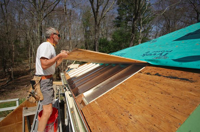
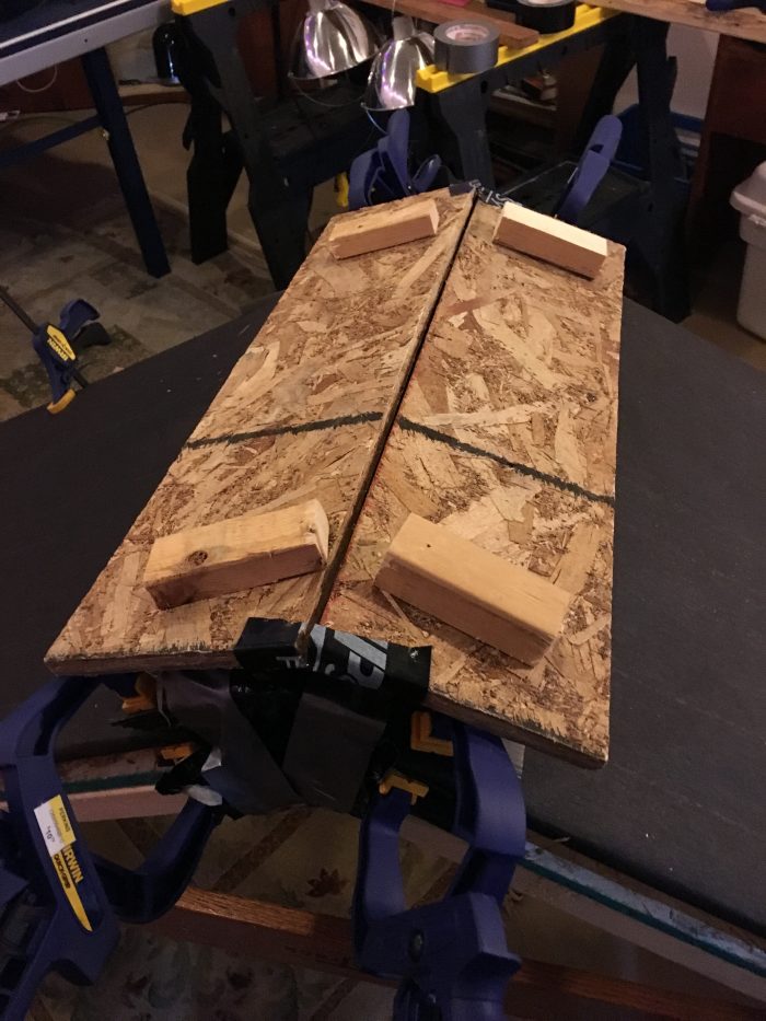
So far, I have performed wingnut testing on PSA tapes and on basement waterproofing products. Very recently, I started working on wingnut testing of roof venting, using an easel made from 2-by lumber and two sandwich panels of 1/2-inch OSB (see the photo above). The easel includes a vent space and ridge vent between the two panels. Each sandwich panel is made up of two layers of OSB, with an air space between the two layers. The easel demo simulates one vented cathedral roof cavity facing one direction and the other facing 180 degrees in the opposite direction.
Frankly, the reason I chose to try to simulate cathedral soffit-to-ridge venting is because it was the easiest to build as an “easel.”
Caveats
Keep in mind that this is wingnut testing. Some caveats:
- I am assuming that this simple easel mimics larger actual roofs.
- I have just gotten started on this testing; there is a lot to work out, and changes will be based on early results. Initial test results are likely to lead to changes in the test protocol; I will be looking for input on the initial approach from many in the building and roofing industry, including ridge vent manufacturers.
- So far I have only tested three ridge vents; there are quite a few more out there.
- I am not releasing the names of the manufacturers of the two ridge vents I have tested because I don’t understand yet why the results are so different, and so far I have not had both of the manufacturers review my test and the results. It only seems fair to take this cautious approach even though it may be way less gratifying to readers of this blog.
Stay tuned; more testing and identification of tested ridge vents soon to follow.
Some background on roof venting
It was Bill Rose and his book “Water in Buildings” that really turned me into a building science wingnut, with a desire to conduct tests in the same vein. (For more on Bill Rose, see this blog by Martin Holladay.) Bill and his book encourage all of us to question building maxims, such as the 1:150 and 1:300 roof venting rules. (For more on attic venting, see “All About Attic Venting.”)
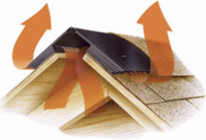
But what about all those arrows in roof ventilation diagrams that sometimes depict air flow? Some of these diagrams are appealing (see Image #1 in the gallery) and some others that seem a lot more creative — or maybe even wishful (see Image #2 in the gallery).
We know that to get air flow through a ventilation channel, we need three things:
- A hole
- Another hole
- A driving force
For driving forces, we have three as well:
- Stack effect
- Wind
- Mechanical (fans)
We will leave mechanically driven air flow (or fan-assisted venting) off on its own for the time being (although there is a lot of GBA content regarding powered roof vents, including “Fans in the Attic”). That leaves us to imagine (or maybe even track) just how wind and stack effect create air flow within roof venting systems.
But boy, there are a lot of variables to consider: the type of venting in attics (soffit-to-ridge or gable-to-gable), the impact of roof pitch, the depth of the vent space, the type and color of roof cladding, the temperatures driving stack effect, the direction and intensity of wind, etc.
Wingnut approach to soffit-to-ridge vent testing in cathedral roof assemblies
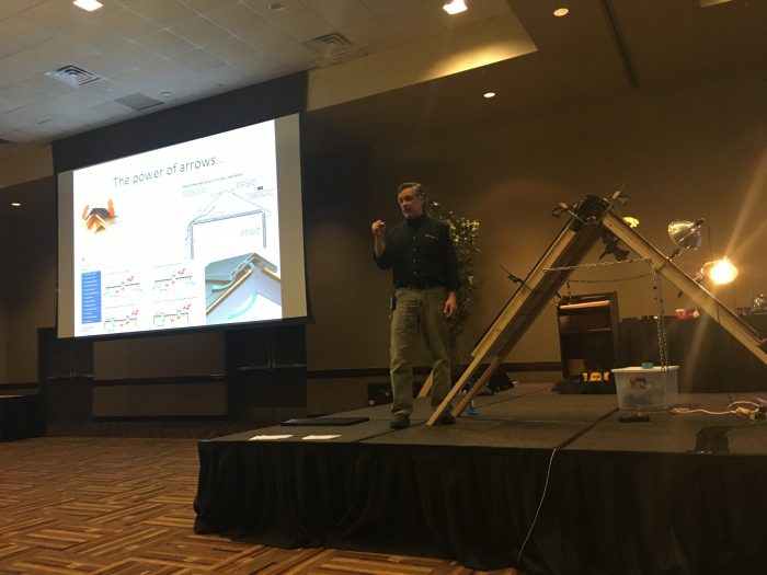
For the last ten years or so, I have been a presenter at the Better Buildings Better Business (B4) conference in the Wisconsin Dells, Wisconsin. It’s a great conference. This year I had three educational sessions on attics and roofs: “Building Science and the Codes”; “Roofs and Attics That Work”; and “Roofs and Attics That Don’t Work.”
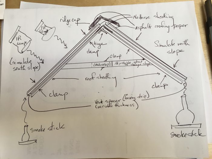
The B4 crowd seems to appreciate and even like building science wingnut testing, so I rigged up what I thought was a decent demo of roof venting and sent this diagram to the conference planner, John Viner, as well as some roofing experts at GAF (see Image #3).
The setup allowed me to pretty easily change:
- Roof vent space depth (3/8”, 3/4”, 1”, 1.5”, 2”);
- Roof pitch (18/12, 12/12, 5/12, 3/12);
- Type of ridge vent;
- The driving forces (stack effect driven by “solar heating” — actually, infrared heat lamps — on one side of the A-frame roof).
I tested two manufactured ridge vents and a home-made ridge cap. The home-made ridge cap consisted of a totally open vent slot capped by a mini-roof made of OSB, with each side of the mini-roof measuring 6 inches wide, and with 1-inch-thick wood block spacers under the OSB to establish a 1-inch-high vent space in the ridge — the same depth as the roof slope vent space depth (see Image #5 in the gallery).
The test consists of:
- Heating up the “south” side of the demo roof with two 250-watt infrared lamps (augmented with a hair dryer as needed) until the surface reaches around 90°F to 100°F;
- Measuring the temperature of the “roof” surface with a digital infrared thermometer;
- A smoke stick test involving a timer (to determine how long it takes the smoke to vent out).
Because of the time crunch getting this test ready for the B4 conference, the tests below are largely qualitative; subsequent testing under more controlled conditions will result in more consistent heated roof temperatures and accurate timing for smoke emergence.
Initial results in my basement
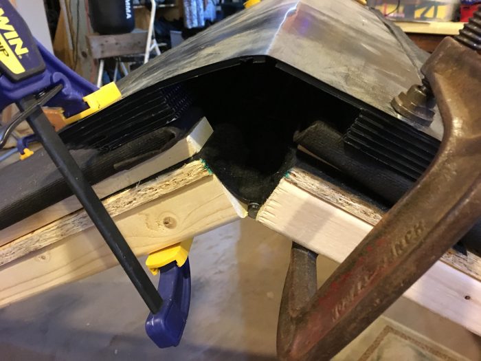
Working by myself, I did not at first figure out how to position the lamps, record the surface temperature, and operate the smoke stick. So there is no video of my first test, which was conducted with the easel at a 18/12 pitch, with a 1-inch vent space, and with a manufactured ridge vent (which I will refer to as Ridge Vent 1 — see Image #4).
You will have to take my word for it: the smoke only came out at the bottom of the opposite roof slope. No smoke came out the manufactured ridge vent at all. What? (If you can’t take my word for it, take a look at the second of the three videos on this page.)
Next, I built a home-made unobstructed OSB ridge vent, which I am going to call Ridge Vent 2 (see Image #5), and repeated the test. Smoke quickly and readily came out the top of the opposite slope, but not the heated side — another unexpected result. (See the video below.)
On to B4 testing
At the B4 conference, we did WTF (Wingnut Test Facility) roof venting testing at the end of each of the three sessions. As happened in my basement testing, Ridge Vent 1 resulted in no smoke coming out the ridge vent but plenty rolling out the bottom of the opposite side of the roof easel (see the video below).
In the video above, you can see a hair dryer being used to augment (speed up) the heating of the “south” side of the demo roof. My initial plan was to use the hair dryer to simulate a different driving force for roof venting — wind — but we ran out of time before we could demonstrate that driving force.
Next, we switched out the ridge vent to another manufactured roof vent (one which I did not have in my basement but that a major roof product manufacturer exhibiting at B4 provided), and this ridge vent worked well — pretty much like the typical arrows depict. I will call this vent Ridge Vent 3 (see the video below).
The results from my basement testing and the testing at the B4 conference were very similar.
- Ridge Vent 1 — a popular manufactured ridge vent — did not have any smoke exiting the ridge; instead, smoke rolled out the bottom of the opposite side.
- Ridge Vent 3 — another popular manufactured ridge vent — had smoke readily exiting the ridge vent, pretty much as depicted in Image #1.
- The unobstructed homemade ridge vent (Ridge Vent 2) had most of the smoke rolling out of the ridge vent on the opposite side.
- Cutting away the insect screening “gauze” on Ridge Vent 1 did very little if anything to improve the lack of smoke exiting at the ridge vent.
- Slope matters; the steeper the slope, the faster the smoke moved out of the roof assembly.
- The depth of the vent space matters; the deeper the vent space, the faster the smoke moved out of the roof assembly.
Image #6 in the gallery shows the taped end of the ridge vent in the demo; we taped off the open ends of each of the ridge vents so that air and smoke did not escape from these unintended openings.
Onward
It sure looks as though we need to learn a lot more about how the arrows should really be drawn for soffit-to-ridge vented cathedral roof assemblies.
I don’t know why the two manufactured roof vents performed so differently and I hope to work with ridge vent manufacturers to better understand why.
I am looking forward to more roof vent testing. I think my initial basement tests and B4 conference tests should inspire more work, particularly:
- Testing more manufactured ridge vents.
- Being more exacting with how much heat is applied and the resulting temperature of the heated roof slope.
- Measuring actual times for each of the tests between smoke starting in at the bottom of the assembly (at the “soffit” or “eave”) and wherever the smoke exits.
Stay tuned for more results in my next GBA blog, and feel free to weigh in with your own insights — and maybe even your own wingnut testing.
Peter Yost is GBA’s technical director. He is also the founder of a consulting company in Brattleboro, Vermont, called Building-Wright. He routinely consults on the design and construction of both new homes and retrofit projects. He has been building, researching, teaching, writing, and consulting on high-performance homes for more than twenty years, and he’s been recognized as NAHB Educator of the Year. Do you have a building science puzzle? Contact Pete here.
Weekly Newsletter
Get building science and energy efficiency advice, plus special offers, in your inbox.


![I have no idea what the driving force is for these arrows. [Image credit: http://eduweb-an.com/flat-roof-vents/flat-roof-vents-nice-roof-shingles-duro-last-roofing]](https://images.greenbuildingadvisor.com/app/uploads/2019/02/20062852/Yost-image-2-resized1-700x705.jpg)
39 Comments
Very cool. I particularly like the smoke rolling out of the bottom of the north slope roof and the farside of the home-made ridge vent. It makes perfect sense once it happens, but it is certainly an unexpected result because it doesn't follow the arrows we always see. I guess the air doesn't read the installation manuals.
I also like the fact that you get more use out of your exercise equipment (the parts from the Nordic Track) than most of us do.
Interesting!
I wonder if there is a way to quantify flow resistance through the cap itself. In other words, decouple it from the driving mechanisms. Perform a sort of blower door test for the caps. Ideally, pressures/flows could be varied to get numbers across a spectrum of conditions. I suspect part of what's going on is resistance caused by friction/differing flow patterns (on the spectrum of laminar vs turbulent flows). High pressure tests may cause a leveling of the playing field in this regard... so doing lower flow/pressure tests would probably be key.
This obviously wouldn't tell us much about the actual driving forces nor how the cap itself might play a dynamic role in altering the driving forces, but it seems it could provide a baseline performance quantification.
The dynamics of the driving forces seem complex and almost endlessly variable. Some factors I could see playing a role in the real world (and you already stated most if not all of these):
--The length, in addition to width and thickness of vent space;
--Air movement over the roof (creating pressure differentials and dynamic flow interactions with the ridge vent shape/baffles);
--Air movement in the locale of the intake (effect of vertical wall and placement of soffit vents in relation to this wall);
--Temperature gradient alterations all the way from exterior of roofing to the underside of the vent chute, and vertically from eaves to ridge. Weather, roof pitch/orientation, and materials would all seemingly play into this.
I've often been curious, too, how much continuous chutes (as in cathedral) differ from cold attics where the chute terminates just past the insulation blanket. The flow boundaries are quite different.
Thanks for your thoughts and comments Tyler.
There certainly is a lot to investigate and I want to determine IF--and if the answer is yes--HOW to accomplish "benchtop" or "wingnut" testing.
To that end, while I was at the International Builders Show, I went to every booth related to roofing and talked about the Wingnut testing and blog, and got some great leads:
1. Benjamin Obdyke's George Caruso has a solid building science background and he and I will be discussing testing and venting issues the middle of next week.
2. More than one ridge vent manufacturer has "smokehouse" demonstrations (such as Air Vent Inc.) that primarily address wind air movement in vents rather than my initial focus on heated "south" roof face as a driver of air flow.
More to come and thanks for sharing ideas regarding driving forces and how to simulate them.
In my article on attic venting, I quoted researcher Jeff Gordon. (Jeff was talking about attic ventilation, not cathedral ceiling ventilation, but his statement is still interesting). I wrote:
"According to Gordon, on a windy day, your attic will be ventilated; when the wind isn’t blowing, don’t expect much ventilation. Gordon wrote, 'What pressures drive attic ventilation? Wind – and that is about it. [There is] little stack effect in the attic – they aren’t very tall. [There] shouldn’t be any induced pressures from mechanical systems (we don’t want duct leakage in the attic). Attic ventilation provides air flow only to the extent that the wind blows.'”
I'll defer to people who have actually done research, but my experience working around attic roofs is that the ridge vent exhausts air even during still weather. The air being vented is much warmer than the ambient conditions, leading me to think it's more likely this temperature difference rather than a pressure one, that is driving the movement.
If wind, (or differences in pressure), is what drives ventilation , why do low-sloped roofs vent so poorly, and experience the problems they do compared to their steeper cousins?
Slope also effects height (soffit to ridge) and changes wind effects. As I recall (can't find the reference), there isn't much difference between north (usually no sun heating) and south side roof performance. Of course solar isn't the only heat source.
I am not convinced that on a still day, stack effect wouldn't have an effect...
but another element that may be at work with low slopes is a reduction in Bernoulli's effect. The lower slope reduces the negative pressure at the ridge some. Like an airplane wing - the longer the path on top, the lower the pressure.
If indeed the air inside the attic is much warmer, it would be at a higher pressure. (Assuming constant volume V, pressure P is proportional to temperature T.) So air inside the attic would want to escape to equalize pressure between inside and outside. Remember your gas law equations from chemistry and physics classes.
With the recent heavy snowfalls in the Twin Cities along with a lack of wind, virtually all roof vents, ridge or otherwise are snow covered. This is aiding in the formation of ice dams as the attic area is in effect an igloo. The snow has been very light and has good insulating properties. I am a strong advocate of vented roof assemblies, adequate R-values and meticulous air sealing are needed in combination.
What do you propose that would maintain (or preferably increase) roof cooling airflow under such conditions?
Jon,
What I am saying is sometimes a vented roof is not vented due to the snow load on the roof. A very well insulated and air sealed attic will perform in this condition where a marginal one may not.
I agree with Martin - wind is the primary driving force, so that's what I'd concentrate on.
IMO, there are so many significant variables that statements like 'a 2" vent will work well and 3/4" won't' are horribly inaccurate approximations.
Two fans move air from my furnace (exhaust and air handler) exactly where and when I want it. Fans are also commonly used to move moisture out of crawlspaces, provide ventilation, cool occupants, cool equipment, etc. Not clear why there is such an aversion to fans correctly applied to roofs. Very predictable, smartly controllable and they don't have to consume significant power (eg solar) or create negative side effects (they can have a positive effect such as offsetting interior stack effect pressures).
Jon,
There are several disadvantages to using fans for roof ventilation:
1. They require an ongoing use of electricity to operate.
2. They require the help of an electrician to install.
3. When a fan breaks or stops working, who notices?
4. If improperly sized, attic fans can depressurize a house and cause backdrafting. (Can we trust installers not to oversize fans? Let me think about that for a while, using the furnace analogy...)
And yet you sometimes suggest installing an exhaust fan in a crawlspace - where the same issues apply.
Jon,
You're absolutely right that the same issues apply to crawl space fans. When I mention them, however, I'm simply repeating code requirements for sealed crawl spaces. (Building codes require sealed crawl spaces to be either pressurized by a forced-air heating and cooling system, or depressurized by an exhaust fan.)
There is no code requirement to use a fan to vent attics.
Apologies if this has been answered, and maybe outside the scope of the wing nut testing (which is super cool) but I’m more curious to understand the ‘why’ of cathedral ceiling venting than the ‘how’.
From my understanding following this site, the heat that builds up on an unvented roof is not meaningfully deleterious to the roofing material, and I can’t understand why a vented-but-not-functionally-so assembly would be much different.
But whereas I don’t care much about cooking, I think I do care about drying. Having a channel below the roof sheathing where moisture from the wood can dissipate seems advantageous to prevent rot and mildew. I would imagine that this drying could occur reasonably well even without much active soffit-to-ridge flow, just by the second law of thermodynamics.
Does that make any sense?
-Max
Max,
The drying mechanism for rainscreens or ventilation channels isn't diffusion -- it's called "ventilation drying," and you definitely need air movement. The more air movement, the faster the drying (as long as the outdoor air isn't too humid, of course).
If you put a damp washcloth in the bottom of a one-gallon glass jar and screw on the lid, the damp washcloth won't dry. If you put a damp washcloth in the middle of a length of PVC pipe with open ends, the washcloth will dry -- because of air movement.
Got it. But if the PVC pipe is horizontal, i.e. no stack effect, and there is zero wind, the washcloth will still dry, right?
Frasca / Max,
If the PVC pipe is horizontal, and there is no stack effect and zero wind, the washcloth will dry (or reach equilibrium with the moisture content of the ambient air) -- eventually.
If you add a mechanical fan, or substantial stack effect flow, or a good wind, it will dry faster. The drying rate depends on the rate of air flow.
If we move away from our washcloth and PVC pipe back to the case of the roof sheathing above a cathedral ceiling, the drying rate matters. One thing is for sure: if you want to avoid sheathing rot, your drying rate has to exceed your wetting rate. If the sheathing gets a little wet due to exfiltration, you want a robust ventilation channel connected to soffit vents and a ridge vent -- because a high rate of drying is better than a slow rate of drying.
Another mechanism which has been brought up here as possibly contributing to the drying of (almost) sealed cavities like walls, and roofs with very small gaps between the sheathing and roofing material, is differential barometric pressure. An interesting wing-nut test might be to take three large jars, add the same amount of water to each, have one with no lid, one with a small hole in the lid and a third sealed.
And then expose it to buffeting wind and significant temperature variation.
Such cavities can also contribute to wetting (depends where they pull incoming air from).
Jon,
Wouldn't that defeat the purpose of the experiment? As I remember, the contexts in which barometric difference has been brought up as being useful as a drying or wetting mechanism have been exterior walls where the air-barrier is towards the outside, basements with thin cavities under the subfloor, and roofs with mesh capillary-breaks under the roofing. The idea would be to see the effects of changing pressure in the context it occurs isolated from changes in temperatures and storms.
I'm sure all such data is useful.
Peter is interested in "air flow through", but "air flow in and then later back out" can also move sometimes significant moisture (even through a single hole). This action is driven by the surrounding pressure (can be called barometric pressure) to cavity pressure difference (which soon re-equalizes). In real cases, a variety of things change these two pressures and most of these would be missing in the case of a jar sitting inside.
Not to belabour the point, but in the case of - say - using a dimple mat under a basement subfloor, what are the things that would cause pressure differences to aid drying that would be absent in the jar test?
Let me know if I'm misinterpreting your comment, but I don't think that changes in atmospheric barometric pressure (i.e., high pressure vs. low pressure weather variations) play into airflow and drying in building cavities. Specifically--the variations of atmospheric pressure are orders of magnitude higher than what occur in buildings: assuming a sea level variation of barometric pressure from 970 mb and 1040 mb, that is 97,000 to 104,000 Pascals (!), or a delta of ~7000 Pascals. If any part of my building is trying to contain 7000 Pascals, I'm running away fast. :)
Of course, barometric pressure in the air is like sea pressure below the water--everything is enveloped in it, so there is no differential unless you have a sealed vessel (e.g., diving bell) to create a difference.
One interesting thing--atmospheric barometric pressure differences *do* create airflow in geometries such as underground caves. I believe that it is a case of small opening, large volume, and lots of friction with the cave walls, which results in storage/capacitance. As a result, with atmospheric pressure changes, wind goes in and out of the cave mouth. See pics below of a journal paper displayed at Jewel Cave National Monument.
"
'Our research shows that the role of thermal buoyancy in diluting attic air with outdoor air is negligible,' says Rose.
This requires rethinking about the design and location of attic vents. For example, some ridge vents may allow air to blow in one side and out the other, without drawing much air from the attic. Rose believes that ridge vents with baffles create better suction to draw air out.
--This article appeared in Energy Source Builder #30 December 1993
©Copyright 1993 Iris Communications, Inc.
"
So there's (at least) two criteria for evaluating a ridge vent:
1) how much resistance does it have to flow (regardless of the engine?)
2) how much power does it contribute to the engine (i.e. does it effectively create/situate in low pressure zones)
3) how well does it keep out unwanted's (snow, rain, etc)
well that's three.
Love it! This is where the old toxic smoke pencils come in with TiO2.... no heat added.
Fully agree, the big red arrow is usually too big and pointing in the wrong direction most of the year like this 2016 SAB Magazine Prize winner in Toronto depicting air flow.
Greg,
My house has a roof top lantern with an operable window. After a very hot day in the summer if I open a window on the first floor and the window in the lantern, I can quite quickly exhaust the hot air in the house and replace it with the cool evening air coming off the coast. This works whether it is windy or still. All I need is a temperature difference.
Malcolm,
It is great to see you using this time tested technology. Barns built over the years had a "cupola" for moving air bottom to top. I did stack hay in some of those barn hay lofts in the summer and it was still very hot, did not cool close to ambient.
https://en.wikipedia.org/wiki/Cupola
Doug,
it works exceedingly well. But perhaps because I would bet I live in one of the few micro-climates where all the factors are there to make it work. Somewhere that cools off very quickly after a hot day, and with little summertime humidity.
I didn't mean to contradict Greg's comments about the illustration he posted. I have very little time for architect's drawings that include fanciful arrows showing airflow. Remember a few years ago when a series of "naturally ventilating" high-rises were proposed based on the ventilation of termite mounds?
https://inhabitat.com/building-modelled-on-termites-eastgate-centre-in-zimbabwe/?variation=c
Malcolm,
I love an open window as much as the next person but its a geography thing. I totally agree stack effect more or less does what the red arrow shows and there's a select few days in the year when you might actually benefit from it unless you're living in a dry, more temperate climate.
The beef I have with the red arrow is that in the seasons where you're paying to condition the indoor air eg. summer air conditioning and winter heating. If you rely on stack effect for summer ventilation -say at night time when it's cooler outside - there may not be a lot of drive (small red arrow!) and the house'd be pulling in cooler yet potentially more humidity if you dried the house with AC during the day. The next hot day, the AC would have to start pulling that latent load out again. In a cold climate winter, the strategy would be wasteful by squanding any indoor heat or humidity.
The big red arrow also means that the main path (big red arrow) gets over-ventilated and any room not in the path likely gets under ventilated. But again, you might be blessed by amazing climate in which case I'm pretty jealous right now. It was a cold bike ride into work this morning.
One thing to consider (and lost in some of our comments) here is that the experiment is set up not to simulate an attic. Instead, the author is attempting to simulate an air gap when no attic is present. This is very different from a typical attic.
I really appreciate the ideas and questions in this string--thanks!
As I stated in the blog, I started with testing air movement in soffit-to-ridge cathedral roof assemblies because it was the easiest to build. I do intend to see if I/we can develop a useful wingnut test approach to other attic/roof configurations.
I would be curious to see the affects of simulating a home where the interior temperature is 70 and exterior temperature is varied from 5 degrees to 80. Wondering if this can be accomplished by a simple box (to simulate the house) that is temperature controlled and a fixed cathedral roof in a environmental chamber?
Peter, you may find the use of a differential pressure sensor useful for your testing. A few examples:
https://www.digikey.com/product-detail/en/nxp-usa-inc/MP3V5010DP/MP3V5010DP-ND/2186183
And
https://www.digikey.com/product-detail/en/amphenol-all-sensors-corporation/1-INCH-D-4V/442-1012-ND/503147
The first is cheap, but the second has better resolution for very low pressures (1” H2O full scale) which might be better suited to your application here. These sensors are just voltage output, so you can just use a voltmeter to get readings from them, no fancy electronics are necassary. You can use vinyl tubing to put extend the sensor ports to various places you want to measure (like the inside and outside of the ridge vent), and then get real measurements of pressure differences created by things like stack effect.
You could probably power these with just a few batteries. I’ve designed barometric pressure sensors using the absolute (non-differential) versions of some of these sensors in the past. They’re very easy to work with.
I love the basement testing by the way! This is the kind of work from which breakthroughs are often made.
Bill
Hi Bill -
just going back through the comments on my first two rounds of Wingnut roof vent testing and reread this one.
I have thought about using pressure (and in the next blog will pull in some really innovative testing that Bill Rose did quite some time ago) but worried what the impact would be of air filled with the "fog" (glycerol compound which is a bit "oily") on my very expensive Retrotec or TEC digital pressure gauges.
The gauges you cite above seem to measure pressure differentials way larger than we would ever get up in a roof assembly? In BIll's work, all the pressures were less than 10 Pa (there are 6894.76 Pa in 1 psi).
Did I miss something in the specs for the gauges you cite above?
Thanks - Peter
A pressure gauge should work just fine inside a plastic bag.
The videos embedded in this article no longer work. Any chance of updating the links?
Thanks for letting us know CL. I'll see if I can reload them asap.
Log in or create an account to post a comment.
Sign up Log in