

More Building Science


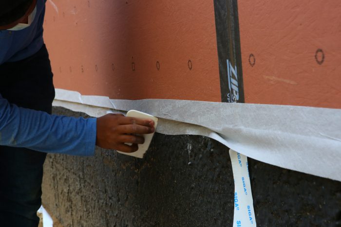
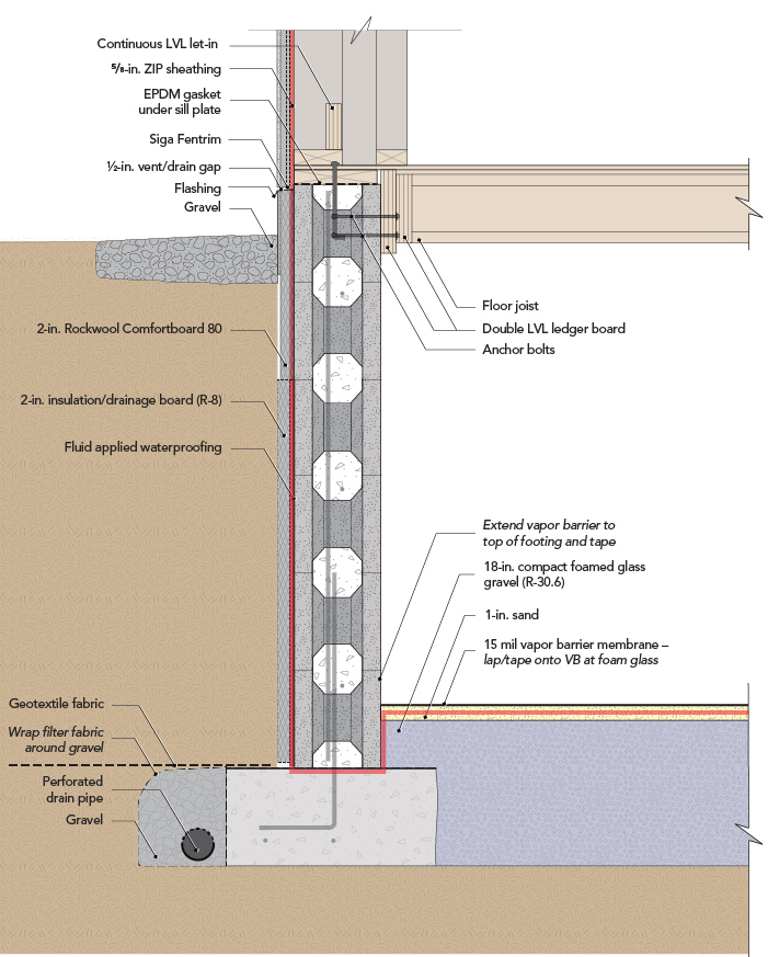
To explain this detail, project manager Ben Bogie runs the equivalent of a verbal pen test, following the air barrier on this net-positive build in New York’s Hudson Valley region. He notes the transition from the ICCF foundation wall to the wood-framed wall integrates a two-part method of control for air leakage. First, an EPDM gasket from Conservation Technology is installed beneath the bottom plates (notably, the team decided against acoustical sealant under the gasket, calling it overkill). Second, they tape from the Zip System sheathing—the primary air barrier—with Siga Fentrim tape down onto the foundation waterproofing.
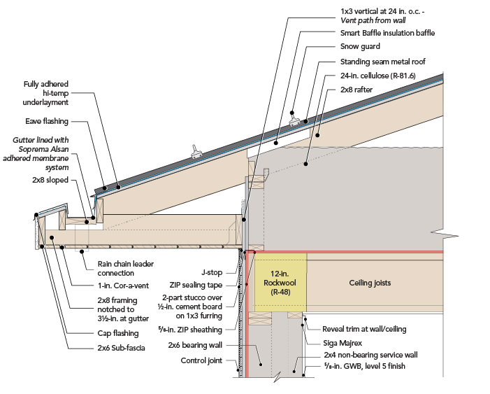
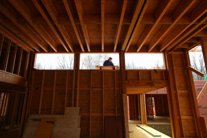
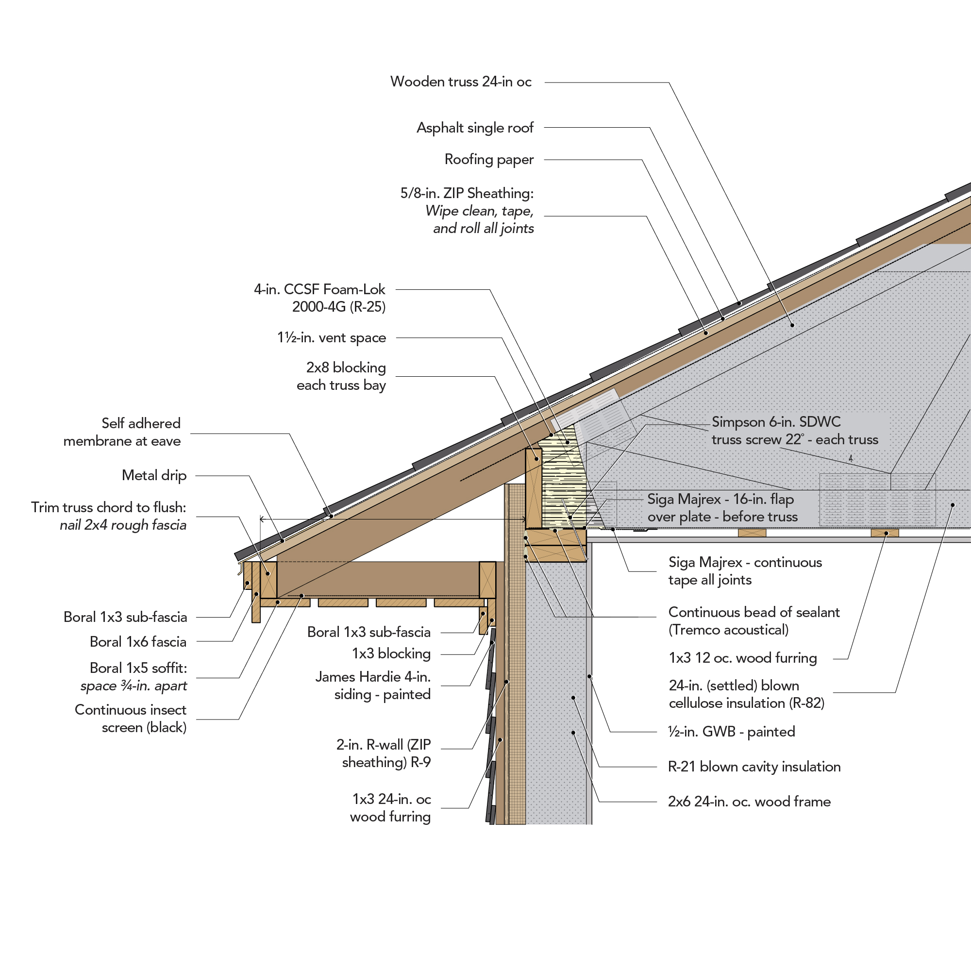
At the ceiling, convention is to stack roof framing on the wall top plates (and then figure out the air barrier). Here, before installing the roof framing, they laid and taped 5/8-in. Zip System panels over the top side of the 14-in. TJI ceiling joists; that’s the air barrier. It makes a turn at the ceiling, crosses over it, and essentially comes down the other side—a continuous line in the pen test.
This is a variation on a method Ben used when working with Dan Kolbert in Portland, Maine—they were installing OSB on the underside of ceiling joists for an air barrier. The method used here has a significant advantage. It creates a 14-in.-deep cavity between the TJI joists to use as a service cavity inside the thermal envelope. “With this size cavity the lighting designer and architect can choose whatever kind of lighting system they want,” Ben notes, “they are not constrained by a small space. Plus, we don’t have to do a bunch of tedious air-sealing around wiring and can lights.”
Using Zip panels or OSB in this location is…
Weekly Newsletter
Get building science and energy efficiency advice, plus special offers, in your inbox.

This article is only available to GBA Prime Members
Sign up for a free trial and get instant access to this article as well as GBA’s complete library of premium articles and construction details.
Start Free TrialAlready a member? Log in


7 Comments
What is the purpose of the LVLs at the base of the 2x6 walls?
Robert,
In an earlier installment of this blog Kiley explained it this way:
"Re: the let-in: The engineer required they notch the bottom of every stud to let in the LVL to distribute the load over the ICCF foundation. (So it was the conservative engineer's response to the unusual block foundation system)."
Thx, makes sense now.
This is getting a little off the topic, but I'm curious about the roof diagram....The gutter embedded in the roof is clever and aesthetically nice. (Plus the rain chain drain somewhere.) Even the southern end of the Hudson Valley can have over a month of below freezing average temps. Isn't this asking for trouble in this climate, with ice buildup trapped in that gutter space? Ice could wreck havoc in an enclosed space. (Not to mention leaf debris accumulation.)
Could someone provide a link to more info on alternative gutter design(s), or maybe post some future article?
Robert,
I don't know if it's justified or not but I've always been leery of recessed gutters.
Here is a link to a project where I think they mesh well with the aesthetic.
https://blog.buildllc.com/2012/09/case-study-house-status/
The ceiling air barrier detail seems very similar to https://www.greenbuildingadvisor.com/article/simple-structure-for-high-performance
this one. A question that has come up is how this works structurally? The detail above is framed more like a very small second story, and uses a ridge beam and collar ties - maybe those things come together to answer my question. But seems like having a break in the vertical structure with a small wall like this on top may have some lateral issues?
I'm no structural engineer, but to my eye, it's the ridge beam that makes it work. Just like if it was a full sized second story with a cathedral ceiling.
Log in or become a member to post a comment.
Sign up Log in